Inst ToolsInst ToolsInst Tools
  • Courses
  • Automation
    • PLC
    • Control System
    • Safety System
    • Communication
    • Fire & Gas System
  • Instrumentation
    • Design
    • Pressure
    • Temperature
    • Flow
    • Level
    • Vibration
    • Analyzer
    • Control Valve
    • Switch
    • Calibration
    • Erection & Commissioning
  • Interview
    • Instrumentation
    • Electrical
    • Electronics
    • Practical
  • Q&A
    • Instrumentation
    • Control System
    • Electrical
    • Electronics
    • Analog Electronics
    • Digital Electronics
    • Power Electronics
    • Microprocessor
  • Request
Search
  • Books
  • Software
  • Projects
  • Process
  • Tools
  • Basics
  • Formula
  • Power Plant
  • Root Cause Analysis
  • Electrical Basics
  • Animation
  • Standards
  • 4-20 mA Course
  • Siemens PLC Course
Reading: Gas Turbine Temperature Alarms using Siemens TIA Portal
Share
Notification Show More
Font ResizerAa
Inst ToolsInst Tools
Font ResizerAa
  • Courses
  • Design
  • PLC
  • Interview
  • Control System
Search
  • Courses
  • Automation
    • PLC
    • Control System
    • Safety System
    • Communication
    • Fire & Gas System
  • Instrumentation
    • Design
    • Pressure
    • Temperature
    • Flow
    • Level
    • Vibration
    • Analyzer
    • Control Valve
    • Switch
    • Calibration
    • Erection & Commissioning
  • Interview
    • Instrumentation
    • Electrical
    • Electronics
    • Practical
  • Q&A
    • Instrumentation
    • Control System
    • Electrical
    • Electronics
    • Analog Electronics
    • Digital Electronics
    • Power Electronics
    • Microprocessor
  • Request
Follow US
All rights reserved. Reproduction in whole or in part without written permission is prohibited.
Inst Tools > Blog > PLC Tutorials > Gas Turbine Temperature Alarms using Siemens TIA Portal

Gas Turbine Temperature Alarms using Siemens TIA Portal

Last updated: March 4, 2021 12:34 pm
Editorial Staff
PLC Tutorials Power Plant
1 Comment
Share
4 Min Read
SHARE

This article is about the temperature alarms PLC program for a Gas turbine. Here we will use Siemens TIA PORTAL for programming the logic.

Contents
Gas Turbine Temperature AlarmsPLC Logic using Siemens TIA PortalProgram Description

There are many applications in the industry where we need to measure the temperature accurately. If the process temperature goes out of the required range then there must be an alarm generated in the system.

Gas Turbine Temperature Alarms

In a Gas turbine, there are various elements need to be monitored like speed, temperature, lube oil pressure, etc.

Here in this article, let’s consider that in the gas turbine we have to measure the temperature in one of the sections.

Here we will take three temperature sensors where RTD PT 100 is used for its constant high accuracy for a smaller range of the temperature measurement. If anyone of the sensors goes out of the range as per the defined temperature setpoint, there should be an alarm generated, which is to notify personnel that things are not working properly.

Also, we want an average of three sensors to maintain a predefined temperature difference. Let’s say, in our case we need to maintain an average temperature of 100°C. We also need one more alarm to indicate, when the average temperature goes out of the range.

If the Temperature difference between Temperature sensor_1 and the average temperature goes above 100°C then the alarm should be generated. Same applicable for sensor_2 and sensor_3.

Whenever there is an active alarm in the system, then I want an additional GENERAL ALARM to be activated.

Here I will use 3 Analog INPUT’s for three RTD temperature sensors and four outputs, out of them one for average temperature indication and three for individual RTD’s.

Inputs:

  • TEMPERATURE SENSOR_1 (MD0)
  • TEMPERATURE SENSOR_2 (MD4)
  • TEMPERATURE SENSOR_3 (MD8)

Outputs:

  • ALARM_1 (Q0.0)
  • ALARM_2 (Q0.1)
  • ALARM_3 (Q0.2)
  • ALARM_4 (Q0.3)

Now first, we need to calculate the average of the temperature readings. For that, we have to add the values of the three temperature sensors and divide it by 3.

Average of 3 Temperature Sensors

PLC Logic using Siemens TIA Portal

Gas Turbine Temperature Alarms using Siemens TIA Portal

Gas Turbine Temperature Control using Siemens Tia Portal

Program Description

Network 1:

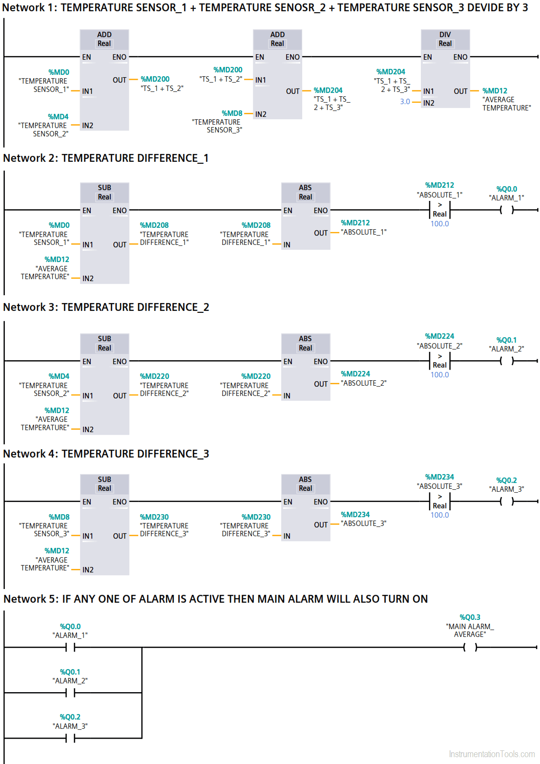
Here, I have added the three temperature sensors readings using ADD instruction and divide it by three as per the above-shown equation to get an average temperature.

Network 2:

Here, we want to generate an alarm, when the difference between Temperature sensor_1 and the average temperature goes above 100 °C. To compare it, we have used greater than instruction.

To generate that difference, I have used subtraction instruction.

Here, absolute instruction is used to reverse the sign (+ or -). If the temperature difference goes negative, we want it to positive using absolute instruction. So, it only alarms when the temperature goes above 100 °C.

Absolute instruction only uses real data type. That’s why we have used data type “real” in all the instructions.

Network 3 & 4:

Here, as explained in the above network Alarm_2 and Alarm_3 generated if the temperature goes above 100°C.

Network 5:

As the temperature difference goes above 100°C from any one of the sensors then the main alarm will also generate.

Author: Suhel Patel

If you liked this article, then please subscribe to our YouTube Channel for PLC and SCADA video tutorials.

You can also follow us on Facebook and Twitter to receive daily updates.

Read Next:

  • Troubleshoot PLC Program
  • Lube Oil Pump Logic
  • PLC Maths Instructions
  • What is PID Controller?
  • PID Controller Loop Tuning
Don't Miss Our Updates
Be the first to get exclusive content straight to your email.
We promise not to spam you. You can unsubscribe at any time.
Invalid email address
You've successfully subscribed !

Continue Reading

PLC Programming to Control Lights in a Sequence
PLC Programming Example with Pushbutton and Motor
PLC Motor Logic with START, STOP, TEST Push buttons
Create Logic with InTouch Scada using Scripting
ICS System Design Considerations
Pulse Timer Instruction in PLC Programming
Share This Article
Facebook Whatsapp Whatsapp LinkedIn Copy Link
Share
1 Comment
  • LAMRI says:
    September 11, 2022 at 1:17 pm

    GOOD, THANK YOU VERY MUCH

    Reply

Leave a Reply Cancel reply

Your email address will not be published. Required fields are marked *

Stay Connected

128.3kFollowersLike
69.1kFollowersFollow
210kSubscribersSubscribe
38kFollowersFollow

Categories

Explore More

Difference between DCS & PLC Systems
Single Loop Controller Questions
Free Schneider PLC Training – Automation Course
Cybersecurity in PLC
PLC Counter Instructions
Control Algorithms in PLC Programming
Types of Limit Switches – Principle, Advantages, Disadvantages
PLC Hoist Crane Programming: Example using Schneider

Keep Learning

PLC Programming for Weight-Based Packaging

PLC Programming for Weight-Based Packaging

VFD Pros and Cons - Variable Frequency Drives

VFD Pros and Cons – Variable Frequency Drives

Single Line Diagram of UPS System

UPS Selection Factors for a Control System

car parking example logic

Up Down Counter Instruction in PLC

Single-acting Cylinder OR operation (PLC and Sensors)

Single-acting Cylinder OR Logic Operation (PLC and Sensors)

Siemens S7 300 CPU Status and LED Errors Explanation

Siemens S7 300 CPU Status and LED Errors Explanation

Simatic 300 Station Configuration

Monitor and Modify Variables in Simatic Manager

SCADA Interview Questions

SCADA Interview Questions and Answers

Learn More

Industrial Light Fittings and Street Light Poles Corrosion Problems

Industrial Light Fittings and Street Light Poles Corrosion Problems

advantages-of-suspension-insulators-and-pin-type-insulators

Advantages of Suspension Insulators and Pin type Insulators

Safety Instrumented System (SIS) Worksheets

Safety Instrumented System (SIS) Worksheets and Documents

solenoid-valves-types-principle-animation

Solenoid Valves Types, Principle & Animation

Instrumentation Documents

Instrument Document Quiz

3-way-2-position-solenoid-valve-spring-return

Pneumatic Directional Control Valves

Calculate LRV and URV for 4-20 mA Loop-powered DP Transmitter

Calculate LRV and URV for 4-20 mA Loop-powered DP Transmitter

calibrating-and-testing-rtd-sensors

RTD Calibration Procedure

Menu

  • About
  • Privacy Policy
  • Copyright

Quick Links

  • Learn PLC
  • Helping Hand
  • Part Time Job

YouTube Subscribe

Follow US
All rights reserved. Reproduction in whole or in part without written permission is prohibited.
Welcome Back!

Sign in to your account

Username or Email Address
Password

Lost your password?