Inst ToolsInst ToolsInst Tools
  • Courses
  • Automation
    • PLC
    • Control System
    • Safety System
    • Communication
    • Fire & Gas System
  • Instrumentation
    • Design
    • Pressure
    • Temperature
    • Flow
    • Level
    • Vibration
    • Analyzer
    • Control Valve
    • Switch
    • Calibration
    • Erection & Commissioning
  • Interview
    • Instrumentation
    • Electrical
    • Electronics
    • Practical
  • Q&A
    • Instrumentation
    • Control System
    • Electrical
    • Electronics
    • Analog Electronics
    • Digital Electronics
    • Power Electronics
    • Microprocessor
  • Request
Search
  • Books
  • Software
  • Projects
  • Process
  • Tools
  • Basics
  • Formula
  • Power Plant
  • Root Cause Analysis
  • Electrical Basics
  • Animation
  • Standards
  • 4-20 mA Course
  • Siemens PLC Course
Reading: Ambient Temperature Effects on RTD
Share
Font ResizerAa
Inst ToolsInst Tools
Font ResizerAa
  • Courses
  • Design
  • PLC
  • Interview
  • Control System
Search
  • Courses
  • Automation
    • PLC
    • Control System
    • Safety System
    • Communication
    • Fire & Gas System
  • Instrumentation
    • Design
    • Pressure
    • Temperature
    • Flow
    • Level
    • Vibration
    • Analyzer
    • Control Valve
    • Switch
    • Calibration
    • Erection & Commissioning
  • Interview
    • Instrumentation
    • Electrical
    • Electronics
    • Practical
  • Q&A
    • Instrumentation
    • Control System
    • Electrical
    • Electronics
    • Analog Electronics
    • Digital Electronics
    • Power Electronics
    • Microprocessor
  • Request
Follow US
All rights reserved. Reproduction in whole or in part without written permission is prohibited.
Inst Tools > Blog > Temperature Measurement > Ambient Temperature Effects on RTD

Ambient Temperature Effects on RTD

Last updated: September 6, 2018 11:35 am
Editorial Staff
Temperature Measurement
1 Comment
Share
3 Min Read
SHARE

Ambient Temperature Effects on 3 Wire RTD

If it is necessary to perform the temperature measurement, some distance away from where the RTD is installed, ambient temperature can have a detrimental effect on the integrity of the measurement.

The reason is that the leads that connect the RTD Sensor to the transmitter, will have resistance of their own, and what is more, this resistance will change with changing ambient temperature. The error introduced by lead resistance, can of course be minimised, if leads with very low resistance is used.

Three Wire RTD Temperature Compensation

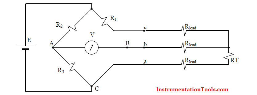
An ingenious approach to the lead resistance problem, is the three wire method, illustrated in above Figure. The three wire method attempts to cancel the effect of the lead resistance, by introducing the same resistance in both branches (wires c and a) of the Wheatstone bridge.

The three wire method is used extensively for industrial RTD’s. Three leads a, b and c, connect to the RTD and the resistance of wires a and c must be matched. This method assumes that the meter is a high impedance device, and that essentially no current is flowing in the b wire, which only acts as a voltage sense lead.

Also Read: Mathematical Proof for RTD Temperature Effects

Ambient Temperature Effects on 4 Wire RTD

The four wire method, depicted in Below Figure, alleviates many problems associated with the Wheatstone bridge.

Instead of using a Wheatstone bridge configuration, a current source is employed to supply a constant current I, to the RTD, through wires a and d.

A high impedance voltmeter M, measures the voltage developed across the RTD, via wires b and c.

Four Wire RTD Temperature Compensation

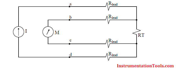
The measured voltage is directly proportional to the resistance of the RTD, so only the conversion from resistance to temperature is necessary. Wires b and c only act as voltage sense leads, and with M a high impedance meter, virtually no current flows in wires b and c, and therefore no voltage drop in these leads and thus no lead resistance error in the measurement.

The disadvantage of the four wire method is that we need one more wire than with the three wire method, but it is a small price to pay if we are at all concerned with the accuracy of the temperature measurement. The four wire method is however gaining in popularity in industry.

Also Read: How RTD Measure Temperature

Don't Miss Our Updates
Be the first to get exclusive content straight to your email.
We promise not to spam you. You can unsubscribe at any time.
Invalid email address
You've successfully subscribed !

Continue Reading

Thermistor Working Principle
Important Factors for Thermocouple Selection
Thermocouples Green Rot Effect
RTD Calculator : Calculate Resistance from Temperature
How to Select Right Thermocouple & Thermowell ?
RTD Testing Methods in Calibration Laboratory
Share This Article
Facebook Whatsapp Whatsapp LinkedIn Copy Link
Share
1 Comment
  • Sandeep kumar says:
    April 27, 2020 at 6:52 pm

    Its very important for our next interviews

    Reply

Leave a Reply Cancel reply

Your email address will not be published. Required fields are marked *

Stay Connected

128.3kFollowersLike
69.1kFollowersFollow
210kSubscribersSubscribe
38kFollowersFollow

Categories

Explore More

Calculate Temperature Coefficient of RTD
Thermocouple Calibration
Thermocouples Burnout detection
Resistance Temperature Detectors Troubleshooting Tips
Difference Between 2 wire RTD, 3 wire RTD, and 4 wire RTD’s
RTD Calculator Software
RTD Standards
Thermocouple Working Principle

Keep Learning

Temperature Measurement Questions

Interview Questions on Temperature Measurement

Use of Temperature Transmitters instead of Direct Wiring

Skin Type Thermocouple

Skin Type Thermocouple

What is an RTD

Components of RTD

Three Wire RTD Circuit

What is a Three-wire RTD ?

Insulation of Thermowell

Facts on Thermowell Insulation Thickness

non-contact pyrometer principle

Non-contact Temperature Sensors

RTD installed after the Orifice Plate

Why RTD installed after the Orifice Plate ?

Learn More

Electronic Devices & Circuits Objective Questions

Electronic Devices & Circuits Quiz – Set 11

Flapper nozzle system

Flapper Nozzle Questions

PLC Programming Software

What Factors Affect the Choice of PLC Programming Software?

U tube Manometer Working

Basics of Pressure

Pilot operated Solenoid Valve Principle

How Pilot operated Solenoid Valve Works ?

Exclusive Valve Sequencing

Exclusive Control Valve Sequence

Top 30 Interview Questions on Pressure Measuring Devices

Top 30 Interview Questions on Pressure Measuring Devices

Principle of Elastic diaphragm gauges

Elastic Diaphragm Gauge Principle

Menu

  • About
  • Privacy Policy
  • Copyright

Quick Links

  • Learn PLC
  • Helping Hand
  • Part Time Job

YouTube Subscribe

Follow US
All rights reserved. Reproduction in whole or in part without written permission is prohibited.
Welcome Back!

Sign in to your account

Username or Email Address
Password

Lost your password?