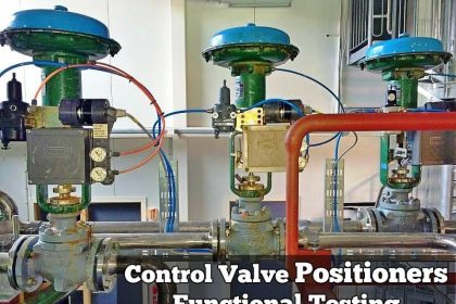
A valve actuator is a device that produces force to open or close the valve utilizing a power source. This source of power can be manual (hand, gear, chain-wheel, lever, etc.) or can be electric, hydraulic or pneumatic.
Basics of Actuators
Basic actuators turn valves to either fully opened or fully closed positions. But modern actuators have much more advanced capabilities. They not only act as devices for opening and closing valves, but also provide intermediate position with high degree of accuracy.
The valve actuator can be packaged together with logic control and digital communication ability to allow remote operation as well as allowing predictive maintenance data.

Type of Actuators
Two types of actuators are common: pneumatic and electric actuators.
Pneumatic:
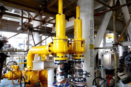
Pneumatic actuators utilize an air signal from an external control device to create a control action via a solenoid. These are commonly available in two main forms: piston actuators and diaphragm actuators.
- Piston actuators – Piston actuators are generally used where the stroke of a diaphragm actuator would be too short or the thrust is too small. The compressed air is applied to a solid piston contained within a solid cylinder. Piston actuators can be single acting or double acting, can withstand higher input pressures, and can offer smaller cylinder volumes which can act at high speed.
- Diaphragm actuators – Diaphragm actuators have compressed air applied to a flexible membrane called the diaphragm. These types of actuators are single acting, in that air is only supplied to one side of the diaphragm, and they can be either direct acting (spring-to-retract) or reverse acting (spring-to-extend).
Their range of applications is enormous. For example, the smallest can deliver a few inch- pounds of torque where the largest are capable of producing in excess of a million inch- pounds of torque.
Electrical Actuators:
Electric actuators are motor driven devices that utilize an electrical input signal to generate a motor shaft rotation. This rotation is, in turn, translated by the unit’s linkage into a linear motion,which drives the valve stem and plug assembly for flow modulation.
In case of electric signal failure, these actuators can be specified to fail in the stem-out, stem-in, or last position. Commonly used motors for electric actuators include steppers and servos.
- A step motor uses gears with increments in the range of 5,000 to 10,000 at 90 degree rotation for accurate positioning at lower speeds. The disadvantage is that steppers may lose synchronization with the controller when employed in an open loop without an encoder or if they are undersized for an application.
- Servos, by definition, are closed loop and provide superior performance at high speeds, but at a higher cost. High precision screws and anti-backlash mechanics provide accuracies to ten-thousandths of an inch. Standard precisions with standard components range from a few hundredths to a few thousandths of an inch.
Brush DC motors and AC motors are sometimes used with limit switches when positioning accuracy is less critical. The motor is connected to a gear or thread that creates thrust to move the valve.
To protect the valve the torque sensing mechanism of the actuator turns off the electric motor when a safe torque level is exceeded. Position switches are utilized to indicate the open and closed position of the valve.
Typically a declutching mechanism and hand wheel are included so that the valve can be operated manually should a power failure occur.
Pneumatic v/s Electric Actuators
The major difference between pneumatic and electronic actuators is the speed of operation. The two technologies are so different that one cannot be a drop-in replacement for the other.
Each has inherent advantages and disadvantages.
Advantages of Pneumatic Actuators
- The biggest advantage of the pneumatic actuators is their failsafe action. By design of the compressed spring, the engineer can determine if the valve will fail closed or open, depending on the safety of the process.
- Provide high force and speed, which are easily adjustable and are independent of each other
- Have a delayed response which makes them ideal for being resilient against small upsets in pressure changes of the source.
- Most economical when the scale of deployment matches the capacity of the compressor.
- Provide inherent safety and are ideal for hazardous and explosive environment.
- Low component cost and smaller footprint.
Limitations of Pneumatic Actuators
Maintenance and operating costs can be high, especially if a serious effort has not been made to quantify and minimize the costs.
Maintenance costs include replacement cylinder costs and plugging air-line leakages whereas the operating costs include the cost of compressed air, i.e. electricity for the compressor.
Electric actuators:
Advantages
- Provide precise control and positioning in comparison to pneumatic actuators.
- Response time is essentially instantaneous.
- High degree of stability.
- Help adapt machines to flexible processes.
- Low operating cost. Controllers and drivers low voltage circuitry consume power to a far lesser degree.
Disadvantages
- The primary disadvantage of an electric actuator is that, should a power failure occur, the valve remains in the last position and the fail-safe position cannot be obtained easily unless there is a convenient source of stored electrical energy.
- Higher cost than pneumatic actuators. High component costs often deter the use of electric actuators because savings in operating costs compared to pneumatics are often not adequately considered or are outright ignored.
- The actuator needs to be in an environment that is rendered safe. Generally not recommended for flammable atmospheres.