Inst ToolsInst ToolsInst Tools
  • Courses
  • Automation
    • PLC
    • Control System
    • Safety System
    • Communication
    • Fire & Gas System
  • Instrumentation
    • Design
    • Pressure
    • Temperature
    • Flow
    • Level
    • Vibration
    • Analyzer
    • Control Valve
    • Switch
    • Calibration
    • Erection & Commissioning
  • Interview
    • Instrumentation
    • Electrical
    • Electronics
    • Practical
  • Q&A
    • Instrumentation
    • Control System
    • Electrical
    • Electronics
    • Analog Electronics
    • Digital Electronics
    • Power Electronics
    • Microprocessor
Search
  • Books
  • Software
  • Projects
  • Process
  • Tools
  • Basics
  • Formula
  • Power Plant
  • Root Cause Analysis
  • Electrical Basics
  • Animation
  • Standards
  • 4-20 mA Course
  • Siemens PLC Course
Reading: Difference between Transparent Level Gauge and Reflex Level Gauge
Share
Notification Show More
Font ResizerAa
Inst ToolsInst Tools
Font ResizerAa
  • Courses
  • Design
  • PLC
  • Interview
  • Control System
Search
  • Courses
  • Automation
    • PLC
    • Control System
    • Safety System
    • Communication
    • Fire & Gas System
  • Instrumentation
    • Design
    • Pressure
    • Temperature
    • Flow
    • Level
    • Vibration
    • Analyzer
    • Control Valve
    • Switch
    • Calibration
    • Erection & Commissioning
  • Interview
    • Instrumentation
    • Electrical
    • Electronics
    • Practical
  • Q&A
    • Instrumentation
    • Control System
    • Electrical
    • Electronics
    • Analog Electronics
    • Digital Electronics
    • Power Electronics
    • Microprocessor
Follow US
All rights reserved. Reproduction in whole or in part without written permission is prohibited.
Inst Tools > Blog > Level Measurement > Difference between Transparent Level Gauge and Reflex Level Gauge

Difference between Transparent Level Gauge and Reflex Level Gauge

Last updated: March 9, 2020 9:12 am
Editorial Staff
Level Measurement
2 Comments
Share
2 Min Read
SHARE

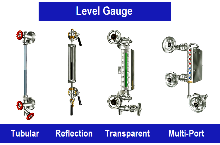
The reflex level gauge uses a prismatic groove as a device to reflect the light if there is a liquid-filled in the chamber. While the transparent level gauge is just simply seen the actual liquid level through the flat glass. Both of them are widely used in the offshore oil & gas projects, but which one we shall use for any specific application?

Contents
Transparent Level Gauge Versus Reflex Level GaugeReflex Level Gauge

Transparent Level Gauge Versus Reflex Level Gauge

Difference between Transparent Level Gauge and Reflex Level Gauge

In general, a transparent level gauge shall be used as the default choice. This is because a transparent level gauge can do what reflex level gauge does but not vice versa. The transparent level gauge is best used in the interface liquid application and also liquid which are not colorless.

If our liquid is colorless, then its recommends using a reflex type level gauge so that the light will not be reflected back to the viewer and the chamber becomes dark. While if it is used on the dirty liquid the light will be reflected back and didn’t give any significant easy to see the liquid level.

The reflex type level gauge also cannot be used in the interface application since it cannot clearly distinguish two different liquid (it just changes to dark when the liquid fills the chamber).

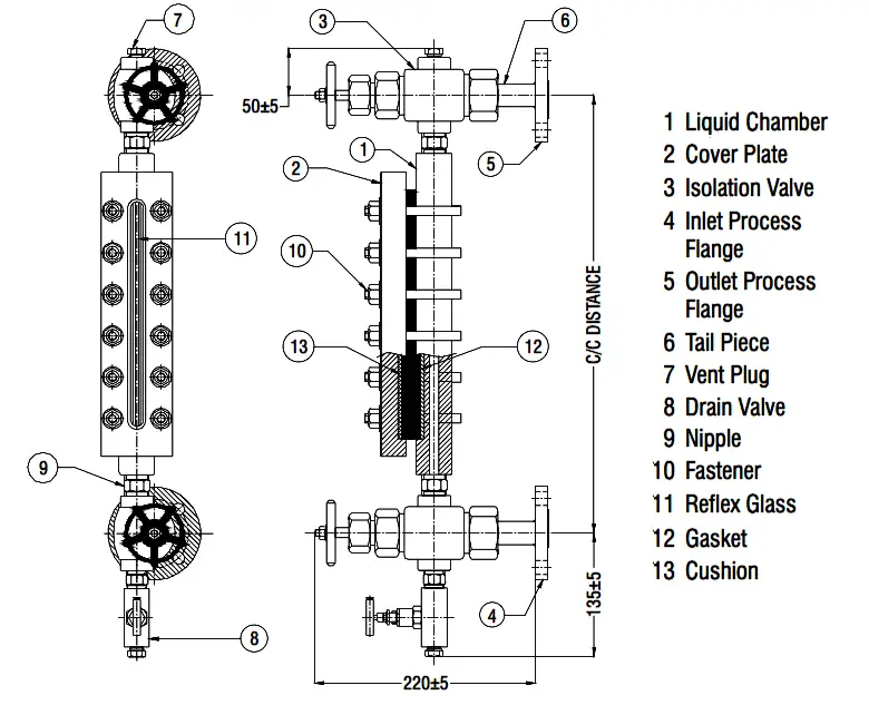
Reflex Level Gauge

Reflex Level Gauge Parts

The transparent level gauge may use such as for diesel+water level, process drain+water, etc.

The reflex level gauge may use such as for MEG (Mono Ethylene Glycol), water level, etc.

Read Next:

  • How to Test a Gauge?
  • Gauge Analog Scale
  • Strain Gauge Principle
  • Pressure Gauge Cocks
  • Failures of Pressure Gauges
Don't Miss Our Updates
Be the first to get exclusive content straight to your email.
We promise not to spam you. You can unsubscribe at any time.
Invalid email address
You've successfully subscribed !

Continue Reading

Capacitance Level Switch Working Principle
What is Displacer Level Sensor ?
Open Tank DP Level Transmitter Calibration
Open Tank Level Measurement using DP Transmitters Animation
Displacer Level Transmitter Calibration using Water & Process Liquid
Ultrasonic Level Switch Principle
Share This Article
Facebook Whatsapp Whatsapp LinkedIn Copy Link
Share
2 Comments
  • suhadi says:
    November 26, 2020 at 12:17 pm

    structure form : basic type with dead zone Conection to Conection distance 1100mm, material Carbon steel, nominal pressure 2.5 Mpa,working temperatur : 250oC, Proses Conection DN20 PN40 RF/T20592-2009

    Reply
  • JohnBannel says:
    April 6, 2024 at 8:52 pm

    very impressive

    Reply

Leave a Reply Cancel reply

Your email address will not be published. Required fields are marked *

Stay Connected

128.3kFollowersLike
69.1kFollowersFollow
208kSubscribersSubscribe
38kFollowersFollow

Categories

Explore More

Radar Tank Gauging
DP Transmitter Interface Level Measurement Principle, Limitations, Selection, Installation, Design & Calibration
Displacer Level Transmitter 5-point Calibration
Ultrasonic Tank Gauging
Ultrasonic Transmitters vs Guided Wave Radar for Level Measurement
Float & Dial Level Gauge Principle
Level Measurement with Wet leg and Installed Below Tapping Point
Nuclear Interface Level Measurement Principle, Limitations, Installation and Calibration

Keep Learning

RF Admittance Level Transmitter Working Principle

RF Admittance Level Transmitter Working Principle

level-transmitter-calibration-procedure

Level Transmitter Calibration Procedure

Nuclear Level Measurement

Nuclear Level Detectors Cascade or Master/Slave concept

Cable Float Level Switch Principle

Cable Float Level Switch Working Principle

Hydrostatic Level Measurement

Hydrostatic Level Measurement

remote seal capillary type dp transmitter

Closed Tank Remote Seal Capillary type DP Transmitter

Dip Tape

What is Dip Tape Level Measurement?

Conductive Level Switch Principle

Conductive Level Switch Principle

Learn More

Feed forward example

What is Feedforward Control ?

Example of PLC Programming based on Logic Circuit

Example of PLC Programming based on Logic Circuit

While Do Statement in Structured Text PLC Program

While Do Statement in Structured Text PLC Program

Location of Pressure Taps

Design Considerations of Orifice Plate

Electromagnetism Objective Questions and Answers

200+ Electromagnetism Objective Questions and Answers

Transistor Collector Feedback Bias

Transistor Collector Feedback Bias

Business Skills Every Engineer Needs

Business Skills Every Engineer Needs

Electronic Devices & Circuits Objective Questions

Electronic Devices & Circuits Quiz – Set 3

Follow US
All rights reserved. Reproduction in whole or in part without written permission is prohibited.
Welcome Back!

Sign in to your account

Username or Email Address
Password

Lost your password?