Inst ToolsInst ToolsInst Tools
  • Ask
  • Courses
  • Videos
  • Q & A
    • Interview
      • Instrumentation
      • Electronics
      • Electrical
      • Practical Questions
    • MCQ
      • Instrumentation MCQ
      • Electrical MCQ
      • Electronics MCQ
      • Control Systems MCQ
      • Analog Electronics MCQ
      • Digital Electronics MCQ
      • Power Electronics MCQ
      • Microprocessor MCQ
      • Multiple Choice Questions
  • EE
    • Electronics
      • Electronics Q & A
      • Electronic Basics
      • Electronic Devices & Circuits
      • Electronics Animation
      • Digital Electronics
    • Electrical
      • Electrical Basics
      • Electrical Q & A
      • Power Electronics
      • Electrical Machines
      • Electrical Animation
      • Power Systems
      • Switchgear & Protection
      • Transmission & Distribution
  • Measure
    • Control Valves
    • Calibration
    • Temperature
    • Pressure
    • Flow
    • Level
    • Analyzers
    • Switches
    • Vibration
    • Solenoid Valve
  • Control
    • PLC Tutorials
    • Control Systems
    • Safety Instrumented System (SIS)
    • Communication
    • Fire & Gas System
  • More
    • Design
    • Tools
    • Animation
    • Basics
    • Formulas
    • Standards
    • TextBooks
    • Common
    • Software
    • Excel Tools
    • Erection & Commissioning
    • Process Fundamentals
    • Videos
    • Books
Search
All rights reserved. Reproduction in whole or in part without written permission is prohibited.
Reading: Function Block (FB) for Motor Control Logic
Share
Notification Show More
Font ResizerAa
Inst ToolsInst Tools
Font ResizerAa
  • Courses
  • PLC Tutorials
  • Control Systems
Search
  • Ask
  • Courses
  • Videos
  • Q & A
    • Interview
    • MCQ
  • EE
    • Electronics
    • Electrical
  • Measure
    • Control Valves
    • Calibration
    • Temperature
    • Pressure
    • Flow
    • Level
    • Analyzers
    • Switches
    • Vibration
    • Solenoid Valve
  • Control
    • PLC Tutorials
    • Control Systems
    • Safety Instrumented System (SIS)
    • Communication
    • Fire & Gas System
  • More
    • Design
    • Tools
    • Animation
    • Basics
    • Formulas
    • Standards
    • TextBooks
    • Common
    • Software
    • Excel Tools
    • Erection & Commissioning
    • Process Fundamentals
    • Videos
    • Books
Follow US
All rights reserved. Reproduction in whole or in part without written permission is prohibited.
Inst Tools > Blog > PLC Tutorials > Function Block (FB) for Motor Control Logic

Function Block (FB) for Motor Control Logic

Last updated: March 4, 2021 2:20 pm
Editorial Staff
PLC Tutorials
2 Comments
Share
5 Min Read
SHARE

How to Create a user-defined Function Block (FB) for Motor Control Logic in Programmable Logic Controllers (PLC).

Contents
Function Block Motor LogicList of Inputs:-List of Outputs:-Memory:-OB1:-Function Block (FB1):-Network 1:-Network 2:-Network 3:-Network 4:-Network 5:-

Function Block Motor Logic

There is one industrial motor and we need to control with FB block logic. Also, consider all interlock like a trip signal, maintenance, etc. Write the PLC program for this logic and configuration.

Function Block Diagram Motor Logic

For this example, we will use the Function block (FB) for motor control logic. Normally START and STOP buttons are used for motor control.

With FBs, the input, output, in/out, and static variables are saved in the instance DB specified in the call statement. The temporary variables are stored in the L stack.

Function block (FB) logic is used for multiple logic applications. For example, there are two industrial motors in the application. Both the motors are operated in the same logic independently. So we will write logic in FB block for one motor function and use the same for other motors as well. (call FB 1 and FB 2 in OB 1).

List of Inputs:-

  • I0.0:- Industrial Motor 1 Start
  • I0.1:- Industrial Motor 1 Stop
  • I0.2:- Industrial Motor 1 Trip
  • I0.3: Maintenance lamp Reset

List of Outputs:-

  • Q0.0:- Industrial Motor On
  • Q0.1:- Fault lamp
  • Q0.2:- Maintenance lamp

Memory:-

  • M0.0:- Motor on command
  • MW10:- Counter value

OB1:-

Organization block for industrial motor 1 logic. FB 1 is called in OB 1.

Here we are using FB1 block only for one motor control. Generally, FB blocks can be called multiple times in a logic depends on the number of motors to control.

If there are more motors in the application, FB 1 can be called for other motors also, no need to write logic every time.

Function Blocks in PLC

Function Block (FB1):-

Function block for logic. In this block, we have declared all temporary variables for motor logic.

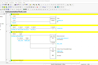
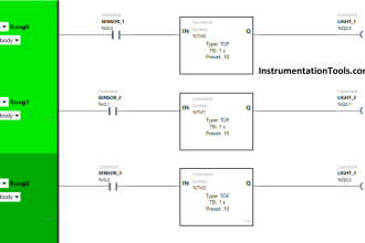
The below-shown ladder logic will be added in our function block FB1, so every time when you call the function block (FB1), it will perform the function as written in the ladder logic.

You can also compare the inputs & outputs labels in the function block (FB1)with respect to the below ladder logic. The function block (FB1) will have the function, inputs, outputs based on this ladder logic only.
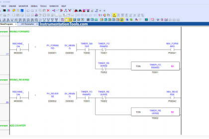
Network 1:-

In this network, motor START/STOP logic is used as per normal motor control logic.

Motor 1 can be started by pressing the START BUTTON (I0.0) and sopped by pressing STOP PB (I0.1).

If trip input (I0.2) triggered, motor ON command (M0.0) will be OFF and motor will be stopped.

Motor Function Block Logic

Network 2:-

When motor command ON, industrial motor (Q0.0) will be ON (Started).

Motor ON Command

Network 3:-

If the Trip command (I0.3) is activated, the fault lamp (Q0.1) will be ON.

Motor Trip Indication Logic

Network 4:-

In this network, counter logic is used for a maintenance lamp. If START BUTTON (I0.0) is pressed for 50 times, the maintenance lamp (Q0.2) will be ON. The counter will be reset after 50 counts.

Lamp Counter Logic

Network 5:-

The maintenance lamp (Q0.2) can be reset by pressing MAINTENANCE RESET BUTTON (I0.4).

Lamp Reset Logic in PLC

As the above explanation, you can write the logic for other motors also. Call FB in OB1 for the second motor and configure the inputs and outputs.

Note:- This is the simple example for FB function used for motor logic in PLC, we can use this concept in other examples also.

Author: Bhavesh

If you liked this article, then please subscribe to our YouTube Channel for PLC and SCADA video tutorials.

You can also follow us on Facebook and Twitter to receive daily updates.

Read Next:

Types of PLC Programming

Motor Control Circuit Wiring

Permissive for Motor Control

What is PID Controller?

Fieldbus Logic and Configuration

Don't Miss Our Updates
Be the first to get exclusive content straight to your email.
We promise not to spam you. You can unsubscribe at any time.
Invalid email address
You've successfully subscribed !
Control Room and Field Instruments Questions and Answers
Motor Control Circuits
Difference Between Industrial Computer (IPC) and Normal Computer (PC)
Industrial Automation Pre-Engineering Design Documents – Project & Process
Concept of DCS in Industrial Automation
Share This Article
Facebook Whatsapp Whatsapp LinkedIn Copy Link
Share
2 Comments
  • vinay tuli says:
    September 27, 2019 at 2:55 pm

    Dear Sir,

    Thanks for your wonderful article. There should be a Print button for Printing in a proper Format so that Printout can be taken .

    If we take printout many unwanted ads , No proper formatting comes.
    Plz look into the suggestion if feasible.

    Reply
  • raja says:
    November 27, 2019 at 9:59 pm

    this is wrong program . the counter will not count up to 50 , cuz every time you press the start switch mw10 will store directly 50 and it will reset the counter again .

    Reply

Leave a Reply Cancel reply

Your email address will not be published. Required fields are marked *

Stay Connected

128.3kFollowersLike
69.1kFollowersFollow
208kSubscribersSubscribe
38kFollowersFollow

Categories

Recent Comments

  • Kamli on Top Free PLC Software
  • Guifty Shimica on Top Non-PLC Certification Courses for Automation Professionals
  • Guifty Shimica on Top Non-PLC Certification Courses for Automation Professionals
  • MIHARITSOA Aina Sitraka on Top Non-PLC Certification Courses for Automation Professionals

Related Articles

Omron PLC Instructions - Move, Move Bit, Move Digit

Move, Move Bit, Move Digit – Examples of Omron PLC Programs

DeMorgan's Theorems

DeMorgan’s Theorems using Ladder Diagram

How to choose between PLC and DCS Systems

How to choose between PLC and DCS Systems ?

RSlogix 500 to communicate with Excel

How to Communicate with Excel from RsLinx?

Functional block diagram for analog alarms

PLC Logic for Analog Alarms using Functional Block Diagram

Traffic Lights Ladder Diagram using Timers

Traffic Lights Ladder Diagram using Timers

How to do Force in GE PLC Proficy Machine Edition?

PLC Ladder Logic for Motor Control

PLC Program for Motor Starter

More Articles

Analyzers Questions and Answers

Silica Analyzer Questions & Answers

Industrial PLC Communication Network

Basics of Industrial Communication Networks

Difference Between Resistive Touch and Capacitive Touch

Difference Between Resistive Touch and Capacitive Touch

simple latching motor control circuit

Motor Control Circuit Wiring

PLC Questions & Answers

Programmable Logic Controller Questions and Answers

How to use Fire Fighting Hydrant

Fire and Safety

Flame Detectors Working Principle

Flame Detectors Working Principle

Installation of a Control Valve

How to Install a Control Valve?

Follow US
All rights reserved. Reproduction in whole or in part without written permission is prohibited.
Welcome Back!

Sign in to your account

Username or Email Address
Password

Lost your password?