Inst ToolsInst ToolsInst Tools
  • Courses
  • Automation
    • PLC
    • Control System
    • Safety System
    • Communication
    • Fire & Gas System
  • Instrumentation
    • Design
    • Pressure
    • Temperature
    • Flow
    • Level
    • Vibration
    • Analyzer
    • Control Valve
    • Switch
    • Calibration
    • Erection & Commissioning
  • Interview
    • Instrumentation
    • Electrical
    • Electronics
    • Practical
  • Q&A
    • Instrumentation
    • Control System
    • Electrical
    • Electronics
    • Analog Electronics
    • Digital Electronics
    • Power Electronics
    • Microprocessor
  • Request
Search
  • Books
  • Software
  • Projects
  • Process
  • Tools
  • Basics
  • Formula
  • Power Plant
  • Root Cause Analysis
  • Electrical Basics
  • Animation
  • Standards
  • 4-20 mA Course
  • Siemens PLC Course
Reading: Draw a Ladder Logic to switch ON-OFF a Bulb using a Toggle Switch ?
Share
Font ResizerAa
Inst ToolsInst Tools
Font ResizerAa
  • Courses
  • Design
  • PLC
  • Interview
  • Control System
Search
  • Courses
  • Automation
    • PLC
    • Control System
    • Safety System
    • Communication
    • Fire & Gas System
  • Instrumentation
    • Design
    • Pressure
    • Temperature
    • Flow
    • Level
    • Vibration
    • Analyzer
    • Control Valve
    • Switch
    • Calibration
    • Erection & Commissioning
  • Interview
    • Instrumentation
    • Electrical
    • Electronics
    • Practical
  • Q&A
    • Instrumentation
    • Control System
    • Electrical
    • Electronics
    • Analog Electronics
    • Digital Electronics
    • Power Electronics
    • Microprocessor
  • Request
Follow US
All rights reserved. Reproduction in whole or in part without written permission is prohibited.
Inst Tools > Blog > PLC Tutorials > Draw a Ladder Logic to switch ON-OFF a Bulb using a Toggle Switch ?

Draw a Ladder Logic to switch ON-OFF a Bulb using a Toggle Switch ?

Last updated: March 4, 2021 3:27 pm
Editorial Staff
PLC Tutorials
No Comments
Share
1 Min Read
SHARE

In the ladder logic diagram we can see there is an input contact (N-O) “I0.0” which is a toggle switch in the physical connections to the plc. There is also an output coil addressed as “Q0.0” which can be a Motor, Bulb or any signaling device in the physical connection.

Ladder Logic
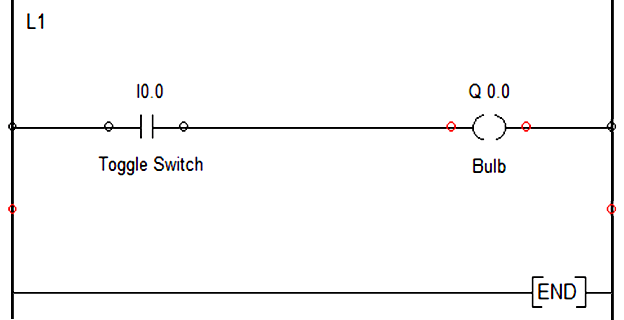
Draw a ladder logic to switch ON-OFF a bulb using a toggle switch

Now, as soon as toggle switch is pressed the NO contact of I0.0 becomes NC and the corresponding rung logic goes true. As a result output coil Q0.0 gets energized and the bulb will ON.

On the other hand, if we want to switch OFF the bulb, the toggle switch is again pressed and I0.0 again becomes an NO contact and rung goes false ,which in turn switches OFF the bulb.

If you liked this article, then please subscribe to our YouTube Channel for PLC and SCADA video tutorials.

You can also follow us on Facebook and Twitter to receive daily updates.

Read Next:
PLC Multiple Choice Questions

Basics of Fail-safe Circuit

PLC Timers Program

Important Question on PLC

What is Seal-in Circuit ?

Don't Miss Our Updates
Be the first to get exclusive content straight to your email.
We promise not to spam you. You can unsubscribe at any time.
Invalid email address
You've successfully subscribed !

Continue Reading

3 to 8 Line Decoder PLC Ladder Diagram
Hardwired I/O and Serial I/O – Differences Explained
Basic PLC Exercise on Heater and Cooler for Students
Basics of Loop Checks
Siemens LOGO PLC Complete Programming Course
Industrial Automation Pre-Engineering Design Documents – Project & Process
Share This Article
Facebook Whatsapp Whatsapp LinkedIn Copy Link
Share
Leave a Comment

Leave a Reply Cancel reply

Your email address will not be published. Required fields are marked *

Stay Connected

128.3kFollowersLike
69.1kFollowersFollow
210kSubscribersSubscribe
38kFollowersFollow

Categories

Explore More

Transferring Data Across PLC Systems – TSEND_C and TRCV_C
PLC Example on Switch Program with Timers
PLC Program for Alarm Security System
Top PLC Manufacturers
Difference between Machine Expert Basic and Machine Expert – Schneider PLC
Siemens S7 300 and STEP 7 PLC program using SIMATIC Software
Difference Between SCADA and HMI
What is Multi-touch Technology? – Industrial Automation

Keep Learning

Wet Contacts and Dry Contacts in PLC Systems

Wet Contacts and Dry Contacts in PLC Systems

Instrumentation Design Details

I&C Engineer Roles & Responsibilities – Instrumentation Design

Difference Between PNP and NPN Sensors

Difference Between PNP and NPN Sensors

DCS Marshalling Cabinet

The Purpose of Marshalling Cabinet or Marshalling Panel

Understanding Braking Theory in VFD

Understanding Braking Theory in VFD

PLC Ladder Program for Automatic Car Wash

PLC Ladder Program for Automatic Car Wash using Siemens TIA Portal

Free Download PLC Book

Free Download Programmable Logic Controller (PLC) Book

Example Program Logic in Allen Bradley PLC

PLC Programming Examples on Industrial Automation

Learn More

Mechanical Engineering Design and Fabrication Projects

300+ Mechanical Engineering Design and Fabrication Projects

IPSec

What is IPSec? – Internet Protocol Security

How Weigh Feeder Works

How Weigh Feeder Works ?

Hammer Handwheel

Valve Handwheel Types : Fixed, Hammer, Gear

Calibration of Pyrometers using Black Body

Calibration of Pyrometers using Black Body

Infrared Flue Gas Analyser

What is Infrared Flue Gas Analyzer? – Working Principle

LIC and FIC Controllers

What LIC and FIC Controllers will do?

Transistor Biasing

Transistor Biasing

Menu

  • About
  • Privacy Policy
  • Copyright

Quick Links

  • Learn PLC
  • Helping Hand
  • Part Time Job

YouTube Subscribe

Follow US
All rights reserved. Reproduction in whole or in part without written permission is prohibited.
Welcome Back!

Sign in to your account

Username or Email Address
Password

Lost your password?