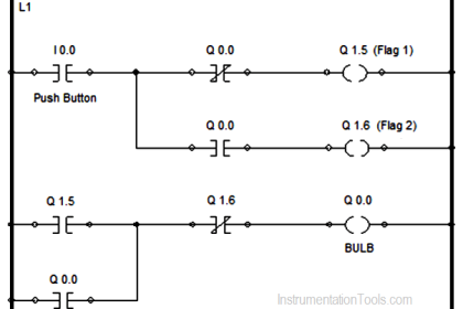
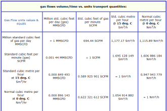
PLC Redundancy Systems may utilize a warm standby, hot standby, or voting configuration as per the design consideration of specific industrial application.
PLC Redundancy

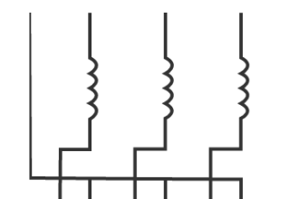
The below Figure shows a typical system configuration for redundant PLCs in either warm or hot standby. Both processors have continuous access to the I/O over redundant buses or networks, and register data and status information are exchanged over a dedicated fiber optic link.

In warm standby configuration, the primary processor is running the program and controlling the output states. Upon failure of the primary processor, the standby processor takes over and begins to run the program.
In a hot standby configuration, both processors are running continuously with their program scans synchronized over the fiber optic link. If one processor fails, the other takes control with a “bumpless” transfer in which the outputs do not change state. The hot standby configuration is recommended for most applications.
Triple-redundant PLC configuration
For highly critical applications, a triple-redundant voting scheme, shown in below figure, may be used.

In this configuration three processors run continuously with synchronized scans, using either shared input data or independent input data from redundant sensors. The outputs of the processors pass through a two-out-of three (2oo3) voter to select the control value to the process.
PLC Components Redundancy
The PLC redundancy options available in different components of PLC.
The different PLC redundancy components are as follows –
-
CPU redundancy :
In case of CPU failure the standby CPU takes care of the plant
-
Power Supply redundancy :
In case the power supply fails the standby power supply takes control of the situation.
-
Communication :
Multiple communication channels are provided to take care of communication failure
-
I/O Redundancy :
Multiple I/O channels are provided to take care of input or output failure.
Types of Redundancy
When it comes to engineering control systems for fault conditions, there many types of redundancies:
- cold,
- warm
- hot
Use of each depends on the criticality of the process and the consequences of equipment failures. And failures are inevitable.
Some processes require less intervention (cold redundancy – a pump failure on a holding tank) while some cannot tolerate any failures or delays (hot redundancy – communication systems. Some are in the middle where automatic action is necessary but the response time is not critical.
Redundancy in engineering systems is about providing reliability and a process alternative to a failing condition.
An alternative response can be designed into a system at the component level (i.e. two processors, two pumps) or at the process level (i.e. two process trains).
The amount of redundancy can be priced in dollar terms which is the total of the extra equipment, installation and manpower. For some critical operations, the total price cannot be tallied because the consequences are too large and the public relations fallout too great (i.e. pipeline leaks). Redundancy helps to ensure business continuity.
Cold Redundancy
Cold redundancy is for non-critical processes where time is not a high priority and human intervention is acceptable.
As an example, if a pressing machine fails, the automation system should notify the operator and issue an alarm. A simple response may be to cut the power supply and displaying a red alarm light. The operator can resume operation by simply starting another unit and requesting service for the failing unit.
Warm Redundancy
When time and response to a failure is more important but not critical, a warm redundancy strategy may suffice if a temporary outage is acceptable.
As an example, if a valve fails to operate on a fluid transfer system, the pump can be disabled and the system shut down. Depending on the process, the product may have a finite period in which it will not be damaged, contaminated or start to deteriorate.
The cycle can tolerate a few seconds or minutes of interruption but the process must be restored quickly and automatically to avoid any integrity issues.
PLC redundancy in warm systems usually operate in shadow mode where they run the identical software and share a heartbeat signal from the primary to the secondary.
An interruption in control with the primary will result in the secondary assuming control. Depending on the process train & components, extra arbitration circuitry may be needed to mux control signals.
THINGS THAT GO BUMP – Since a fault can happen at any moment during a program, it may take a few program scans for the changeover to complete. The standby processor may have incomplete or stale data that may result in a process bump and glitch to the product.
Hot Redundancy
Warm & hot redundancy are similar in architecture but hot redundancy that offers instant process correction when a failure is detected.
For example, in a mining or ore operation, if a primary controller for a conveyor fails, a backup one should immediately assume control to avoid any delays in the transfer.
The PLC programming software & hardware coordination must be solid to allow for constant messaging between processors and access to common data to allow for a smooth transition.
Data can be transferred between processors or accessed through a common database located on the network. Either way, the secondary process must have knowledge of every logic cycle as to where the primary left off.
Data Transfer Methods for Hot Redundant Systems
Data can be transferred at the end of each program scan. This is the most popular method where data is transferred to the other processor before the next scan begins.
Program control must be designed properly since the combined program scan and data transfer may exceed the critical timing of the specific application. One way to minimize the scan time is to limit the number of run executions on each ladder to only when a logic condition has changed.
Some PLCs come with two processors in the same unit. One is dedicated to program execution and the other to data transfer to the backup PLC. Program design is simplified as it does not need to be optimized for scan time.
Redundancy in industrial control systems is critical for the safety of equipment, employees and even the public. Three types of redundancy can be used, depending on how critical the process needs to be controlled. Understanding and implementing the right redundancy strategy will result in a reliable system when equipment fail. And everything will eventually fail.
If you liked this article, then please subscribe to our YouTube Channel for PLC and SCADA video tutorials.
You can also follow us on Facebook and Twitter to receive daily updates.
Read Next:
Instrumentation Control System