Inst ToolsInst ToolsInst Tools
  • Courses
  • Automation
    • PLC
    • Control System
    • Safety System
    • Communication
    • Fire & Gas System
  • Instrumentation
    • Design
    • Pressure
    • Temperature
    • Flow
    • Level
    • Vibration
    • Analyzer
    • Control Valve
    • Switch
    • Calibration
    • Erection & Commissioning
  • Interview
    • Instrumentation
    • Electrical
    • Electronics
    • Practical
  • Q&A
    • Instrumentation
    • Control System
    • Electrical
    • Electronics
    • Analog Electronics
    • Digital Electronics
    • Power Electronics
    • Microprocessor
  • Request
Search
  • Books
  • Software
  • Projects
  • Process
  • Tools
  • Basics
  • Formula
  • Power Plant
  • Root Cause Analysis
  • Electrical Basics
  • Animation
  • Standards
  • 4-20 mA Course
  • Siemens PLC Course
Reading: PLC Ladder Logic for Sensor Scaling with Offset
Share
Font ResizerAa
Inst ToolsInst Tools
Font ResizerAa
  • Courses
  • Design
  • PLC
  • Interview
  • Control System
Search
  • Courses
  • Automation
    • PLC
    • Control System
    • Safety System
    • Communication
    • Fire & Gas System
  • Instrumentation
    • Design
    • Pressure
    • Temperature
    • Flow
    • Level
    • Vibration
    • Analyzer
    • Control Valve
    • Switch
    • Calibration
    • Erection & Commissioning
  • Interview
    • Instrumentation
    • Electrical
    • Electronics
    • Practical
  • Q&A
    • Instrumentation
    • Control System
    • Electrical
    • Electronics
    • Analog Electronics
    • Digital Electronics
    • Power Electronics
    • Microprocessor
  • Request
Follow US
All rights reserved. Reproduction in whole or in part without written permission is prohibited.
Inst Tools > Blog > PLC Tutorials > PLC Ladder Logic for Sensor Scaling with Offset

PLC Ladder Logic for Sensor Scaling with Offset

Last updated: March 4, 2021 4:02 pm
Editorial Staff
PLC Tutorials
No Comments
Share
3 Min Read
SHARE

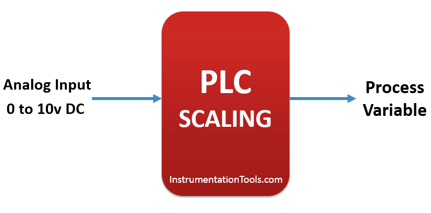
This is PLC Ladder Logic for Sensor Scaling with Offset. Make PLC program for the analog input scaling for several scales used in general applications.

Contents
PLC Ladder Logic for Sensor Scaling with OffsetSolutionList of Inputs/OutputsLadder Diagram for Pressure and Temperature SensorsLadder Logic Description

PLC Ladder Logic for Sensor Scaling with Offset

PLC Ladder Logic for Sensor Scaling with Offset

Solution

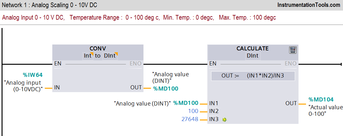
Here we consider different analog scale for explanation. Consider 0-10V DC analog input signal for this examples. We will use different scaling equation for the analog inputs like Temperature and Pressure Sensors.

Analog value is in current or voltage form so we need to convert this value into actual value. Here 0-10 V DC value is converted to actual value with instructions.

List of Inputs/Outputs

List of Inputs

  • IW 64:-Analog input channel

M memory

  • MD100 :-Analog value
  • MD104 :-Actual value (0-100 degree).
  • MD108 :-Analog value
  • MD112 :-Actual pressure (0-200 bars).

Ladder Diagram for Pressure and Temperature Sensors
PLC Scaling for Temperature Sensor
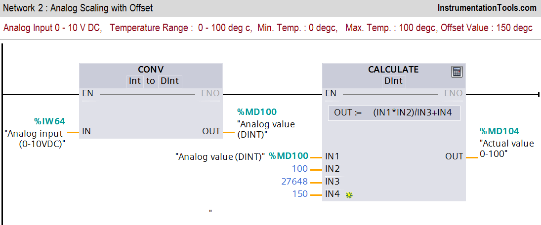
PLC Scaling for Temperature Sensor with Offset Value
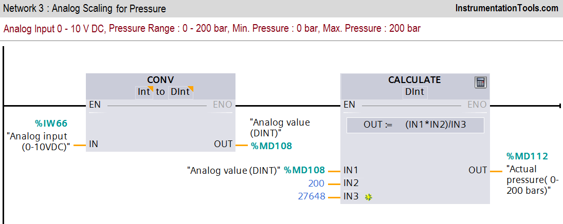
Pressure Sensor Scaling in PLC
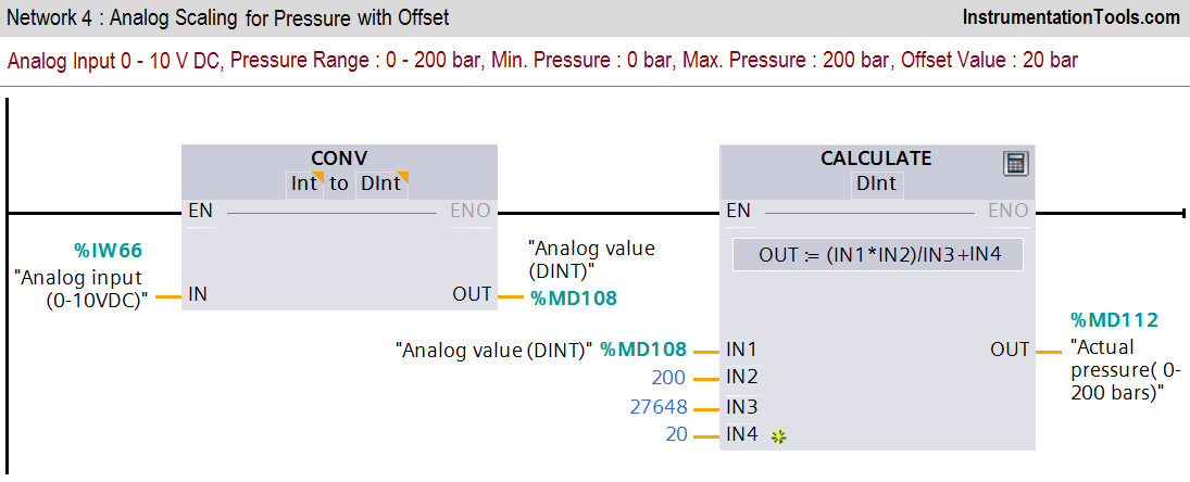
PLC Offset Logic Diagram

Ladder Logic Description

Network 1 :-

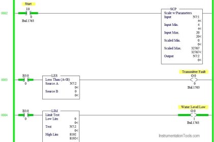
In first network we have converted analog value into actual temperature. Actual analog value is in INT form so we need to convert in DINT for calculation purpose.

Here maximum temperature is 100 degree and minimum temperature is 0 degree.

Network 2 :-

In this network offset value (150 degree) is added into scaling.

Network 3 :-

In this network we have taken pressure sensor scaling for the application. Pressure is scaled in the range between (0-200 bars).

Network 4 :-

In this network offset value (20 bar) is added into scaling as offset value.

Note:-

Above application may be different from actual application. This example is only for explanation purpose only. We can implement this logic in other PLC also. This is the simple application for several scales of analog value using PLC, we can use this concept in other examples also.

All parameters and graphical representations considered in this example are for explanation purpose only, parameters or representation may be different in actual applications. Also all interlocks are not considered in the application.

Author : Bhavesh

If you liked this article, then please subscribe to our YouTube Channel for PLC and SCADA video tutorials.

You can also follow us on Facebook and Twitter to receive daily updates.

Read Next:
Quiz on PLC

PLC Counters Program

Boiler logic using PLC

Compressor Control Logic

Conveyor using PLC Logic

Don't Miss Our Updates
Be the first to get exclusive content straight to your email.
We promise not to spam you. You can unsubscribe at any time.
Invalid email address
You've successfully subscribed !

Continue Reading

PLC Controlled Conveyor and Weighing with Labeling Automation
PLC Trainer Demo Download
SCADA Communication and Protocols
Sequential PLC Programming for the Pneumatic Valves
Communication between InTouch Scada and Allen Bradley PLC
Difference Between Wifi and Industrial Wireless
Share This Article
Facebook Whatsapp Whatsapp LinkedIn Copy Link
Share
Leave a Comment

Leave a Reply Cancel reply

Your email address will not be published. Required fields are marked *

Stay Connected

128.3kFollowersLike
69.1kFollowersFollow
210kSubscribersSubscribe
38kFollowersFollow

Categories

Explore More

VFD Commissioning and Testing Procedure (Variable Frequency Drive)
Elevator PLC Ladder Logic
Automatic Car Washing using PLC
One Shot Rising and One Shot Falling Instructions in PLC
PLC Permissive for Motor Control
PLC Ladder Logic Design: Control 3 Motors with Toggle Switch
Gas Turbine Temperature Alarms using Siemens TIA Portal
Network Switch Requirement in SCADA and DCS Architecture

Keep Learning

Site Acceptance Test (SAT) of PLC System

PLC System Site Acceptance Test (SAT)

Control Methods in Servo Motor Drives

Various Control Methods in Servo Motor Drives

PLC FBD Programming for Burglar Alarm Security System

PLC FBD Programming for Burglar Alarm Security System

What is a Tag in SCADA

What is a Tag? Types of Tags in SCADA

Free WinCC SCADA Training Course

Free SCADA Training Course

Shutdown Motors in Timed Operation PLC Program

Shutdown Motors in Timed Operation PLC Program

Indusoft SCADA Modbus Communication

Establishing a Modbus Driver for SCADA Indusoft Web Studio

What is Ladder Diagram Programming ?

Learn More

Measurement of Impedance Objective Questions

Measurement of Impedance Objective Questions

Sensors and Transducers Objective Questions

Transducers Objective Questions

Power System Protection Multiple Choice Questions

Power System Protection Multiple Choice Questions

Flow Standards

Flow Standards

Positive Feedback Principle

What is an Oscillator ?

Thermography and Thermometry Objective Questions

Thermography and Thermometry Objective Questions

Ladder Rung with Two Outputs

PLC Multiple Outputs Configuration

Guide to vibration severity per ISO 10816

Importance of Vibration Measurement

Menu

  • About
  • Privacy Policy
  • Copyright

Quick Links

  • Learn PLC
  • Helping Hand
  • Part Time Job

YouTube Subscribe

Follow US
All rights reserved. Reproduction in whole or in part without written permission is prohibited.
Welcome Back!

Sign in to your account

Username or Email Address
Password

Lost your password?