Inst ToolsInst ToolsInst Tools
  • Ask
  • Courses
  • Videos
  • Q & A
    • Interview
      • Instrumentation
      • Electronics
      • Electrical
      • Practical Questions
    • MCQ
      • Instrumentation MCQ
      • Electrical MCQ
      • Electronics MCQ
      • Control Systems MCQ
      • Analog Electronics MCQ
      • Digital Electronics MCQ
      • Power Electronics MCQ
      • Microprocessor MCQ
      • Multiple Choice Questions
  • EE
    • Electronics
      • Electronics Q & A
      • Electronic Basics
      • Electronic Devices & Circuits
      • Electronics Animation
      • Digital Electronics
    • Electrical
      • Electrical Basics
      • Electrical Q & A
      • Power Electronics
      • Electrical Machines
      • Electrical Animation
      • Power Systems
      • Switchgear & Protection
      • Transmission & Distribution
  • Measure
    • Control Valves
    • Calibration
    • Temperature
    • Pressure
    • Flow
    • Level
    • Analyzers
    • Switches
    • Vibration
    • Solenoid Valve
  • Control
    • PLC Tutorials
    • Control Systems
    • Safety Instrumented System (SIS)
    • Communication
    • Fire & Gas System
  • More
    • Design
    • Tools
    • Animation
    • Basics
    • Formulas
    • Standards
    • TextBooks
    • Common
    • Software
    • Excel Tools
    • Erection & Commissioning
    • Process Fundamentals
    • Videos
    • Books
Search
All rights reserved. Reproduction in whole or in part without written permission is prohibited.
Reading: Differences between No-load Supply Current and Load Current
Share
Notification Show More
Font ResizerAa
Inst ToolsInst Tools
Font ResizerAa
  • Courses
  • PLC Tutorials
  • Control Systems
Search
  • Ask
  • Courses
  • Videos
  • Q & A
    • Interview
    • MCQ
  • EE
    • Electronics
    • Electrical
  • Measure
    • Control Valves
    • Calibration
    • Temperature
    • Pressure
    • Flow
    • Level
    • Analyzers
    • Switches
    • Vibration
    • Solenoid Valve
  • Control
    • PLC Tutorials
    • Control Systems
    • Safety Instrumented System (SIS)
    • Communication
    • Fire & Gas System
  • More
    • Design
    • Tools
    • Animation
    • Basics
    • Formulas
    • Standards
    • TextBooks
    • Common
    • Software
    • Excel Tools
    • Erection & Commissioning
    • Process Fundamentals
    • Videos
    • Books
Follow US
All rights reserved. Reproduction in whole or in part without written permission is prohibited.
Inst Tools > Blog > Instrumentation Design > Differences between No-load Supply Current and Load Current

Differences between No-load Supply Current and Load Current

Last updated: June 8, 2018 11:38 am
Editorial Staff
Instrumentation Design
1 Comment
Share
5 Min Read
SHARE

The current consumption of an industrial sensor is a very important consideration. Knowing the current consumption of all your devices on a machine allows you to size wire properly and pick the right power supply for the application.

Differences between No-load Supply Current and Load Current

There are two specifications on a data sheet that are worth looking at. The first is the no-load supply current and the second is the load current.

No-Load Supply Current

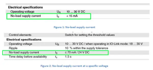
When sizing a power supply, this is the most important specification to look at. No-load supply current is the amount of current that a device consumes when the device is just sitting there. This current is consumed no matter if there is a load attached to the output or not. In Figure 1, you see that this sensor has a current consumption of 15 mA or less. This value is the current consumption maximum over all voltage and temperature ranges. Sometimes the current consumption is specified at a specific voltage like in Figure 2.

No Load Supply Current vs Load Supply current

Load Current

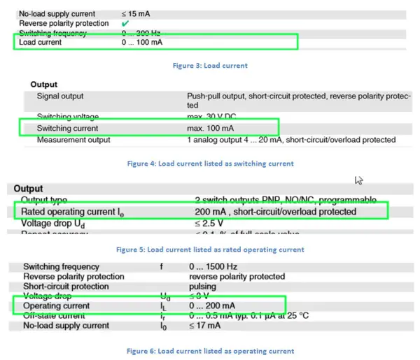
This specification is the most misunderstood. Load current simply tells the user how much current the industrial sensor can supply to a load. It is not the amount of current that a sensor will supply to a load. You really need to know what load is connected to the sensor to know how to size the power supply. 95% of all sensors used today are connected to very low current I/O cards. An I/O card has a fixed load current and will consume between 3 mA and 9 mA at 24 VDC depending on the hardware design.

This current is consumed only when the sensor is switched and the output turns on. Needless to say, you always assume, when sizing a power supply, that all sensors are on all the time. You always plan for a worst-case scenario and you want a safety margin designed into your system. This specification of load current has many names in a catalog or data sheet and they include Load Current (Figure 3), Switching Current (Figure 4), Rated Operating Current (Figure 5), and Operating Current (Figure 6).

No Load Supply Current vs Load Supply current 2

Just make sure that the load current rating from the data sheet of the sensor is greater than the current consumption of the input card.

For example, an input module has an input current of 9 mA. If the allowed maximum load current of the sensor is 100 mA, which is much larger than 9 mA, the sensor will function properly and the sensor will not be overloaded.

Input current of sensor datasheet

The total current consumption of the sensor is the no-load supply current of the sensor plus the input current of the module or I/O card. For example, if the no-load supply current is 15 mA (Figure 1) and the input current is 9 mA (Figure 7), then the total current consumed is 15 mA + 9 mA, which equals 24 mA. This is the number you would use to size your power supply for that sensor.

Conclusion

Sometimes the data sheets give you more information than you really need. Use the no-load supply current and the current consumption of the I/O module to come up with the total current consumption of your sensor. Then, as an extra check, make sure that the allowed maximum load current of the sensor is larger than the input current on the module or I/O card. Now that you have the current consumption for one sensor, do this for all sensors on your entire machine. You can now size the cable and power supplies properly.

Source : P & F
Don't Miss Our Updates
Be the first to get exclusive content straight to your email.
We promise not to spam you. You can unsubscribe at any time.
Invalid email address
You've successfully subscribed !
Solenoid Operated Valves and Latching Valves
Draw a ladder logic circuit for the electric motor of an air compressor ?
Competency Factors of Instrument & Control Engineer (Design Engineering)
Basic Calculations of Instrument Air
Pressure Control Valves vs Pressure Regulators
Share This Article
Facebook Whatsapp Whatsapp LinkedIn Copy Link
Share
1 Comment
  • Aditya Mekha says:
    July 6, 2016 at 6:38 pm

    Thank you so much for sharing your valuable knowledge..

    Reply

Leave a Reply Cancel reply

Your email address will not be published. Required fields are marked *

Stay Connected

128.3kFollowersLike
69.1kFollowersFollow
208kSubscribersSubscribe
38kFollowersFollow

Categories

Recent Comments

  • Guifty Shimica on Top Non-PLC Certification Courses for Automation Professionals
  • Guifty Shimica on Top Non-PLC Certification Courses for Automation Professionals
  • MIHARITSOA Aina Sitraka on Top Non-PLC Certification Courses for Automation Professionals
  • Vaishnavi on Free Instrumentation Course for Trainee Engineers

Related Articles

Thermowell Problems

Thermowell Problems

Pressure Gauge Datasheet

How to Fill up Instrument Datasheet? – Pressure Gauge Specifications & Standards

Transmitter Range and Sensor Limits

Transmitter Minimum Span, Accuracy & Turndown

30 Concerns for Control System Philosophy (Industrial Automation)

30 Concerns for Process Control Systems Philosophy

Flow Control Valves

Difference Between a Flow Control & a Needle Valve

Normally closed input actuator as stop button.

Normally-Closed Contacts for Stop Buttons

History of 3-15 psi, 10-50 mA, and 4-20 mA signals

History of 3-15 psi, 10-50 mA, and 4-20 mA signals

Important Factors Consider during Piping Design

Important Factors Consider during Piping Design

More Articles

Gate Array Logic using PLC

PLC Program to Simulate Gate Array Logic

RF Level Sensors Principle

RF Level Switches Working Principle

DC Circuits Multiple Choice Questions

DC Circuits Multiple Choice Questions

Self-balancing Pneumatic Instrument Principles - 3

Self-balancing Pneumatic Instrument Principles

level control system

Practical Process Control System Questions & Answers – 11

transmitter calibration procedure

Transmitter Calibration Procedure

Gearbox within week Failing Journal Bearing upset Plant Operations

Gearbox within week Failing Journal Bearing upset Plant Operations

Simatic Hardware Configuration

Configuration of Profibus Network in Siemens PLC

Follow US
All rights reserved. Reproduction in whole or in part without written permission is prohibited.
Welcome Back!

Sign in to your account

Username or Email Address
Password

Lost your password?