Inst ToolsInst ToolsInst Tools
  • Courses
  • Videos
  • Q & A
    • Interview
      • Instrumentation
      • Electronics
      • Electrical
      • Practical Questions
    • MCQ
      • Instrumentation MCQ
      • Electrical MCQ
      • Electronics MCQ
      • Control Systems MCQ
      • Analog Electronics MCQ
      • Digital Electronics MCQ
      • Power Electronics MCQ
      • Microprocessor MCQ
      • Multiple Choice Questions
  • EE
    • Electronics
      • Electronics Q & A
      • Electronic Basics
      • Electronic Devices & Circuits
      • Electronics Animation
      • Digital Electronics
    • Electrical
      • Electrical Basics
      • Electrical Q & A
      • Power Electronics
      • Electrical Machines
      • Electrical Animation
      • Power Systems
      • Switchgear & Protection
      • Transmission & Distribution
  • Measure
    • Control Valves
    • Calibration
    • Temperature
    • Pressure
    • Flow
    • Level
    • Analyzers
    • Switches
    • Vibration
    • Solenoid Valve
  • Control
    • PLC Tutorials
    • Control Systems
    • Safety Instrumented System (SIS)
    • Communication
    • Fire & Gas System
  • More
    • Design
    • Tools
    • Animation
    • Basics
    • Formulas
    • Standards
    • TextBooks
    • Common
    • Software
    • Excel Tools
    • Erection & Commissioning
    • Process Fundamentals
    • Videos
    • Books
Search
All rights reserved. Reproduction in whole or in part without written permission is prohibited.
Reading: Electric Motor Actuator Parts
Share
Notification Show More
Font ResizerAa
Inst ToolsInst Tools
Font ResizerAa
  • Courses
  • PLC Tutorials
  • Control Systems
Search
  • Courses
  • Videos
  • Q & A
    • Interview
    • MCQ
  • EE
    • Electronics
    • Electrical
  • Measure
    • Control Valves
    • Calibration
    • Temperature
    • Pressure
    • Flow
    • Level
    • Analyzers
    • Switches
    • Vibration
    • Solenoid Valve
  • Control
    • PLC Tutorials
    • Control Systems
    • Safety Instrumented System (SIS)
    • Communication
    • Fire & Gas System
  • More
    • Design
    • Tools
    • Animation
    • Basics
    • Formulas
    • Standards
    • TextBooks
    • Common
    • Software
    • Excel Tools
    • Erection & Commissioning
    • Process Fundamentals
    • Videos
    • Books
Follow US
All rights reserved. Reproduction in whole or in part without written permission is prohibited.
Inst Tools > Blog > Control Valves > Electric Motor Actuator Parts

Electric Motor Actuator Parts

Last updated: March 21, 2019 11:48 am
Editorial Staff
Control Valves
No Comments
Share
5 Min Read
SHARE

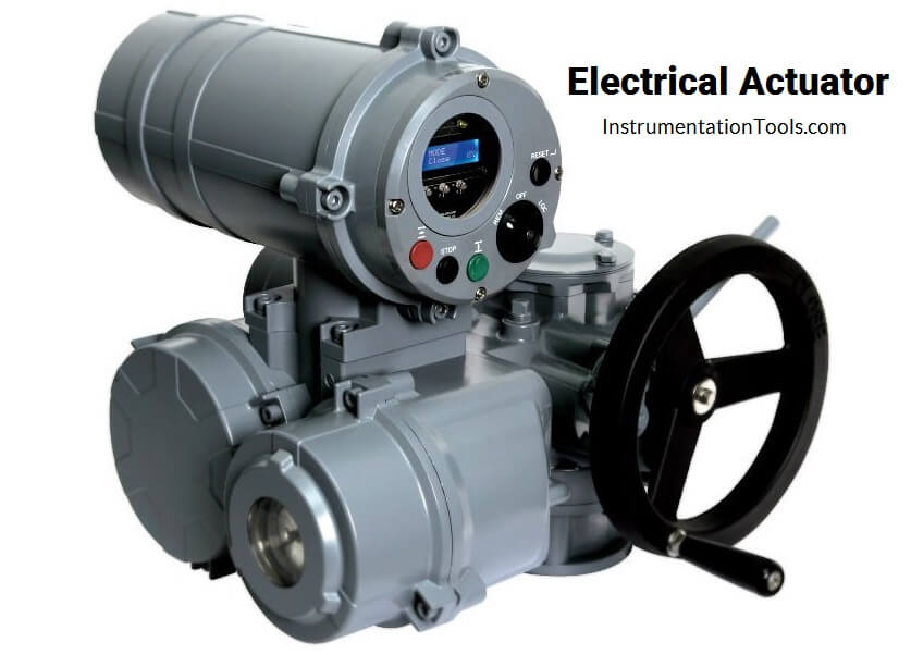
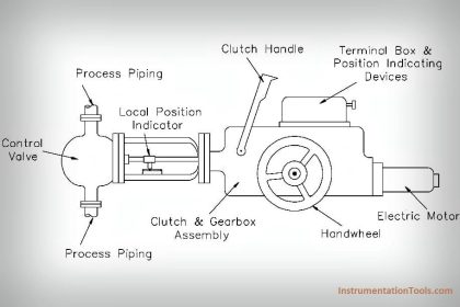
The electric actuator uses an electric motor to provide torque to operate a valve. They are quiet, non-toxic and energy efficient. However, electricity must be available, which is not always the case, they can also operate on batteries.

Contents
Electric Motor Actuator PartsMotorLimit and Torque SensorsGearingValve attachmentManual operationActuator controlsElectrical connectionFieldbus connection

Electric Motor Actuator Parts

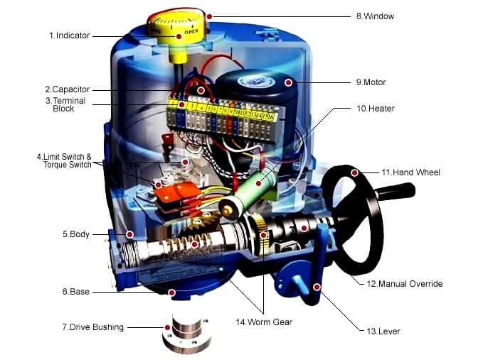
Electrical Motor Actuator Parts

Motor

Robust asynchronous three-phase AC motors are mostly used as the driving force, for some applications also single-phase AC or DC motors are used. These motors are specially adapted for valve automation as they provide higher torques from standstill than comparable conventional motors, a necessary requirement to unseat sticky valves.

The actuators are expected to operate under extreme ambient conditions, however they are generally not used for continuous operation since the motor heat buildup can be excessive.

Limit and Torque Sensors

The limit switches signal when an end position has been reached. The torque switching measures the torque present in the valve. When exceeding a set limit, this is signaled in the same way.

Actuators are often equipped with a remote position transmitter which indicates the valve position as continuous 4-20mA current or voltage signal.

Gearing

Often a worm gearing is used to reduce the high output speed of the electric motor. This enables a high reduction ratio within the gear stage, leading to a low efficiency which is desired for the actuators.

The gearing is therefore self-locking i.e. it prevents accidental and undesired changes of the valve position by acting upon the valve’s closing element.

Valve attachment

The valve attachment consists of two elements. First: The flange used to firmly connect the actuator to the counterpart on the valve side. The higher the torque to be transmitted, the larger the flange required.

Second: The output drive type used to transmit the torque or the thrust from the actuator to the valve shaft. Just like there is a multitude of valves there is also a multitude of valve attachments.

Dimensions and design of valve mounting flange and valve attachments are stipulated in the standards EN ISO 5210 for multi-turn actuators or EN ISO 5211 for part-turn actuators. The design of valve attachments for linear actuators is generally based on DIN 3358.

Manual operation

In their basic version most electric actuators are equipped with a handwheel for operating the actuators during commissioning or power failure. The handwheel does not move during motor operation.

The electronic torque limiting switches are not functional during manual operation. Mechanical torque-limiting devices are commonly used to prevent torque overload during manual operation.

Electric Motor Actuator Parts

Actuator controls

Both actuator signals and operation commands of the DCS are processed within the actuator controls. This task can in principle be assumed by external controls, e.g. a PLC.

Modern actuators include integral controls which process signals locally without any delay. The controls also include the switchgear required to control the electric motor. This can either be reversing contactors or thyristors which, being an electric component, are not subject to mechanic wear.

Controls use the switchgear to switch the electric motor on or off depending on the signals or commands present. Another task of the actuator controls is to provide the DCS with feedback signals, e.g. when reaching a valve end position.

Electrical connection

The supply cables of the motor and the signal cables for transmitting the commands to the actuator and sending feedback signals on the actuator status are connected to the electrical connection.

The electrical connection can be designed as a separately sealed terminal bung or plug/socket connector. For maintenance purposes, the wiring should be easily disconnected and reconnected.

Fieldbus connection

Fieldbus technology is increasingly used for data transmission in process automation applications. Electric actuators can therefore be equipped with all common fieldbus interfaces used in process automation.

Special connections are required for the connection of fieldbus data cables.
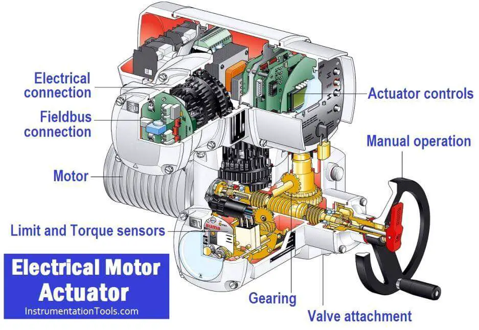
Electrical Motor Actuator Components

Don't Miss Our Updates
Be the first to get exclusive content straight to your email.
We promise not to spam you. You can unsubscribe at any time.
Invalid email address
You've successfully subscribed !

Continue Reading

How to Protect Pumps from Cavitation? – Reasons, Solutions
Quick Exhaust and Air Operated Valves in Instrumentation Circuit
Control Valve Stroke Test Procedure
What are Isolation valves? – Purpose, Types, Configurations
What is Globe Valve ?
Control Valve Fail Safe Action
Share This Article
Facebook Whatsapp Whatsapp LinkedIn Copy Link
Share
Leave a Comment

Leave a Reply Cancel reply

Your email address will not be published. Required fields are marked *

Stay Connected

128.3kFollowersLike
69.1kFollowersFollow
208kSubscribersSubscribe
38kFollowersFollow

Categories

Explore More

Compare Solenoid Valve Manual Reset and Solenoid Manual Override
Difference between PCV and PRV
Speed of Actuators
Control Valve Flow Direction
What is Ball Valve ?
Fundamentals of Valves and their Types
Basics of Valves
Short Notes on Different Valve Types
What is a 2-way Solenoid Valve ?
Directional Control Valves Working Principle

Keep Learning

Valves MCQ

Valves MCQ

Difference-between-pneumatic-electric-hydraulic-actuators

Difference between Pneumatic, Electrical & Hydraulic Actuators

Control Valve Positioners

Control Valve Positioners

Common Valve Abbreviations

Common Valve Abbreviations in US Engineering Drawings

Difference between Rotary Shaft and Sliding Stem Control Valves

Difference between Rotary Shaft Valves and Sliding Stem Control Valves

How to do Control Valve Sizing

How do you do control valve sizing in Layman’s terms?

CONTROL VALVE CHARACTERISTICS

Difference between Quick Opening, Linear & Equal Percentage Control Valve characteristics

Kv-value of a valve is determined by a standardised test

Calculate Flow Coefficient Kv of Solenoid Valve

Discover More

NH3 Storage Tanks Ammonia Gas

NH3 Storage Tanks Ammonia Gas Venting Issue – Root Cause Analysis

Control Valve in Nutshell - Valve Design and Selection Factors

Control Valve in Nutshell – Valve Design and Selection Factors

diode-clamper-circuit

Diode Clampers Principle

Foundation Fieldbus Signal Conversion Formula

Foundation Fieldbus Signal Conversion Formula

Oscillators and Signal Generators Objective Questions

Oscillators and Signal Generators Objective Questions

Digital Electronics Multiple Choice Questions

Demultiplexers Objective Questions

PLC Ladder Logic Example based on Set Coil and Reset Coil

PLC Ladder Logic Example based on Set Coil and Reset Coil

What is Temperature

What is Temperature ?

Follow US
All rights reserved. Reproduction in whole or in part without written permission is prohibited.
Welcome Back!

Sign in to your account

Username or Email Address
Password

Lost your password?