Inst ToolsInst ToolsInst Tools
  • Courses
  • Videos
  • Q & A
    • Interview
      • Instrumentation
      • Electronics
      • Electrical
      • Practical Questions
    • MCQ
      • Instrumentation MCQ
      • Electrical MCQ
      • Electronics MCQ
      • Control Systems MCQ
      • Analog Electronics MCQ
      • Digital Electronics MCQ
      • Power Electronics MCQ
      • Microprocessor MCQ
      • Multiple Choice Questions
  • EE
    • Electronics
      • Electronics Q & A
      • Electronic Basics
      • Electronic Devices & Circuits
      • Electronics Animation
      • Digital Electronics
    • Electrical
      • Electrical Basics
      • Electrical Q & A
      • Power Electronics
      • Electrical Machines
      • Electrical Animation
      • Power Systems
      • Switchgear & Protection
      • Transmission & Distribution
  • Measure
    • Control Valves
    • Calibration
    • Temperature
    • Pressure
    • Flow
    • Level
    • Analyzers
    • Switches
    • Vibration
    • Solenoid Valve
  • Control
    • PLC Tutorials
    • Control Systems
    • Safety Instrumented System (SIS)
    • Communication
    • Fire & Gas System
  • More
    • Design
    • Tools
    • Animation
    • Basics
    • Formulas
    • Standards
    • TextBooks
    • Common
    • Software
    • Excel Tools
    • Erection & Commissioning
    • Process Fundamentals
    • Videos
    • Books
Search
All rights reserved. Reproduction in whole or in part without written permission is prohibited.
Reading: Oil and Water Separation Process using PLC Programming
Share
Notification Show More
Font ResizerAa
Inst ToolsInst Tools
Font ResizerAa
  • Courses
  • PLC Tutorials
  • Control Systems
Search
  • Courses
  • Videos
  • Q & A
    • Interview
    • MCQ
  • EE
    • Electronics
    • Electrical
  • Measure
    • Control Valves
    • Calibration
    • Temperature
    • Pressure
    • Flow
    • Level
    • Analyzers
    • Switches
    • Vibration
    • Solenoid Valve
  • Control
    • PLC Tutorials
    • Control Systems
    • Safety Instrumented System (SIS)
    • Communication
    • Fire & Gas System
  • More
    • Design
    • Tools
    • Animation
    • Basics
    • Formulas
    • Standards
    • TextBooks
    • Common
    • Software
    • Excel Tools
    • Erection & Commissioning
    • Process Fundamentals
    • Videos
    • Books
Follow US
All rights reserved. Reproduction in whole or in part without written permission is prohibited.
Inst Tools > Blog > PLC Tutorials > Oil and Water Separation Process using PLC Programming

Oil and Water Separation Process using PLC Programming

This is a PLC Program for the automatic water separation process. Learn ladder logic with the example problems.

Last updated: November 3, 2023 12:25 pm
Editorial Staff
PLC Tutorials
2 Comments
Share
5 Min Read
SHARE

This is a PLC Program for the automatic water separation process. Learn ladder logic with the example problems.

Contents
Oil and Water Separation ProcessProblem DiagramProblem SolutionI/O ListList of inputsList of outputsM memoryPLC Ladder DiagramPLC Program DescriptionNetwork 1:Network 2:Network 3:Network 4:Network 5:Network 6:Result

Oil and Water Separation Process

Problem Description

Implement oil and water separation process in PLC using ladder diagram programming language.

Problem Diagram

PLC Program for Automatic Oil and Water Separation Process

Problem Solution

We will use PLC S7-300 for this application. We will use scaling for programming purpose.

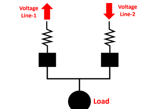
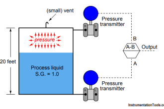
Due to the gravitational force and density of water and oil, when oil and water both are present in liquid, oil always resides on the top of the water. By using this concept we have made one arrangement for oil and water separation as shown in figure.

However, this system is not completely removing water particles from the mixed liquid but only less than 10% of water contents are presents after this process.

Temperature transmitter is used to control the temperature in the tank and level transmitter is used to control or display the level of the tank.

Here, for monitoring purpose it is considered that level is 200cm and temperature is 50 degree centigrade.

Level sensors are used for controlling the oil control valve.

I/O List

List of inputs

  • Cycle START :- I0.0
  • Cycle STOP :- I0.1
  • High level :- I1.1
  • Low level :- I1.0
  • Level transmitter input :- IW64 (analog)
  • Temperature transmitter :- IW66 (analog)

List of outputs

  • Oil outlet valve :- Q0.0

M memory

  • Master coil :- M0.0
  • LT_input DINT : – MD100 (DINT)
  • Multiplication value :- MD104
  • Actual level :- MD108
  • TT_input DINT :- MD112
  • Multiplication value :- MD116
  • Actual temperature :- MD120

PLC Ladder Diagram

PLC Logic for Automatic Oil and Water Separation Process
Oil and Water Separation Process
water separation process
PLC Oil water
PLC Separation Process
PLC Programming Water

PLC Program Description

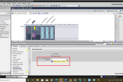
For this application, we used S7-1200 PLC and TIA portal software for programming.
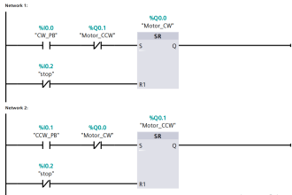
Network 1:

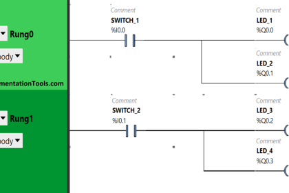
we used latching circuit for master coil (M0.0) output. It can be started by pressing START PB (I0.0) and stop by pressing STOP PB (I0.1).

Network 2:

When high level (I1.1) is detected and low level (I1.0) is not detected, oil outlet valve (Q0.0) will be ON.

Network 3:

Here actual count or value coming from the level transmitter is current (4 to 20mA) so by using analog input channel in the PLC we can convert it into digital count.

This digit is in INT (IW64) format so we need to convert it into DINT (MD100) for calculation or multiplication.

Network 4:

DINT value (MD100) is multiplied with max height (200cm) of the tank for calculation purpose.

The multiplied value (MD104) is divided by max count of the analog module (27648).And final actual level is stored in MD108.

Network 5:

Here actual count or value coming from the temperature transmitter is current (4 to 20mA) so by using analog input channel in the PLC we can convert it into digital count.

This digit is in INT (IW66) format so we need to convert it into DINT (MD112) for calculation or multiplication.

Network 6:

DINT value (MD112) is multiplied with max temp (100 degree) of the tank for calculation purpose. The multiplied value (MD116) is divided by max count of the analog module (27648).And final actual temperature is stored in MD120.

Note:- Above application may be different from actual application. This example is only for explanation purpose only. We can implement this logic in other PLC also. This is the simple concept of oil and water separation process, we can use this concept in other examples also.

All parameters considered in example are for explanation purpose only, parameters may be different in actual applications. Also all interlocks are not considered in the application.

Result

Automatic Oil and Water Separation Process

Author: Bhavesh

If you liked this article, then please subscribe to our YouTube Channel for PLC and SCADA video tutorials.

You can also follow us on Facebook and Twitter to receive daily updates.

Read Next:

  • PLC Problems Troubleshooting
  • Failsafe Wiring Practices
  • PLC Sinking and Sourcing
  • Digital Signals Wiring Techniques
  • PLC Program Examples
Don't Miss Our Updates
Be the first to get exclusive content straight to your email.
We promise not to spam you. You can unsubscribe at any time.
Invalid email address
You've successfully subscribed !

Recommended Articles

PID Controllers in Closed Loop Control Systems – PLC Basics
PLC Cooking Timer Example for Kitchen Automation
PLC Programming Example for a Batch Process
Flexible Input Output Modules
MCQ on PLC (Programmable Logic Controller)
What is a Control Panel and its types?
Share This Article
Facebook Whatsapp Whatsapp LinkedIn Copy Link
Share
2 Comments
  • Phil says:
    September 23, 2018 at 1:53 am

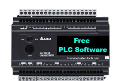
    What is TIA portal software?

    Reply
  • sridhar says:
    June 22, 2020 at 8:00 pm

    super explanation for basics

    Reply

Leave a Reply Cancel reply

Your email address will not be published. Required fields are marked *

Stay Connected

128.3kFollowersLike
69.1kFollowersFollow
208kSubscribersSubscribe
38kFollowersFollow

Categories

Recent Comments

  • William Snyder on Top Non-PLC Certification Courses for Automation Professionals
  • Kamli on Top Free PLC Software
  • Guifty Shimica on Top Non-PLC Certification Courses for Automation Professionals
  • Guifty Shimica on Top Non-PLC Certification Courses for Automation Professionals

Related Articles

PLC Logic - Control Spray Nozzle, Fans, and Puncher

PLC Logic: Control Spray Nozzle, Fans, and Puncher

Exhaust Fan Control

Exhaust Fan Control: Example of PLC Timer Programming

PLC Program for Analog Input Sampling

PLC Analog Input Sampling Ladder Logic

Switched Mode Power Supply (SMPS)

How does SMPS Works? – Switched Mode Power Supply

Electrical Cabinet Air Conditioner

Electrical Cabinet Air Conditioner – Enclosure Cooling, Maintenance

Best Practices of PLC Wiring

Best Practices of PLC Wiring – Programmable Logic Controller

PLC Data Logging and Transmission

Moving Data between PLCs – Siemens Basics – TSEND TRCV

SCADA Systems

SCADA Systems

More Articles

Probability of failure on demand (PFD)

Probability of Failure on Demand (PFD)

How to Run Multiple Motors with a Single VFD

How to Run Multiple Motors with a Single VFD?

PLC Data Logging and Transmission

Moving Data between PLCs – Siemens Basics – TSEND TRCV

Pressurizer

Pressurizer

Calibration of Temperature Sensor with Indicator

Calibration of Temperature Sensor with Indicator

Axial Diaphragm Seal Connection

Difference between Axial and Radial Diaphragm Seal Connection?

State Variable Analysis and Design

Diagonalization

Automatic Car Washing Process using PLC Ladder Diagram

Automatic Car Washing using PLC

Follow US
All rights reserved. Reproduction in whole or in part without written permission is prohibited.
Welcome Back!

Sign in to your account

Username or Email Address
Password

Lost your password?