Inst ToolsInst ToolsInst Tools
  • Ask
  • Courses
  • Videos
  • Q & A
    • Interview
      • Instrumentation
      • Electronics
      • Electrical
      • Practical Questions
    • MCQ
      • Instrumentation MCQ
      • Electrical MCQ
      • Electronics MCQ
      • Control Systems MCQ
      • Analog Electronics MCQ
      • Digital Electronics MCQ
      • Power Electronics MCQ
      • Microprocessor MCQ
      • Multiple Choice Questions
  • EE
    • Electronics
      • Electronics Q & A
      • Electronic Basics
      • Electronic Devices & Circuits
      • Electronics Animation
      • Digital Electronics
    • Electrical
      • Electrical Basics
      • Electrical Q & A
      • Power Electronics
      • Electrical Machines
      • Electrical Animation
      • Power Systems
      • Switchgear & Protection
      • Transmission & Distribution
  • Measure
    • Control Valves
    • Calibration
    • Temperature
    • Pressure
    • Flow
    • Level
    • Analyzers
    • Switches
    • Vibration
    • Solenoid Valve
  • Control
    • PLC Tutorials
    • Control Systems
    • Safety Instrumented System (SIS)
    • Communication
    • Fire & Gas System
  • More
    • Design
    • Tools
    • Animation
    • Basics
    • Formulas
    • Standards
    • TextBooks
    • Common
    • Software
    • Excel Tools
    • Erection & Commissioning
    • Process Fundamentals
    • Videos
    • Books
Search
All rights reserved. Reproduction in whole or in part without written permission is prohibited.
Reading: Ammeter
Share
Notification Show More
Font ResizerAa
Inst ToolsInst Tools
Font ResizerAa
  • Courses
  • PLC Tutorials
  • Control Systems
Search
  • Ask
  • Courses
  • Videos
  • Q & A
    • Interview
    • MCQ
  • EE
    • Electronics
    • Electrical
  • Measure
    • Control Valves
    • Calibration
    • Temperature
    • Pressure
    • Flow
    • Level
    • Analyzers
    • Switches
    • Vibration
    • Solenoid Valve
  • Control
    • PLC Tutorials
    • Control Systems
    • Safety Instrumented System (SIS)
    • Communication
    • Fire & Gas System
  • More
    • Design
    • Tools
    • Animation
    • Basics
    • Formulas
    • Standards
    • TextBooks
    • Common
    • Software
    • Excel Tools
    • Erection & Commissioning
    • Process Fundamentals
    • Videos
    • Books
Follow US
All rights reserved. Reproduction in whole or in part without written permission is prohibited.
Inst Tools > Blog > Electrical Theory > Ammeter

Ammeter

Last updated: August 7, 2018 11:47 pm
Editorial Staff
Electrical Theory
No Comments
Share
4 Min Read
SHARE

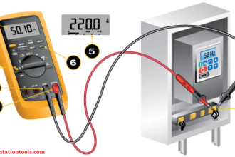
The ammeter measures electric current. It may be calibrated in amperes, milliamperes, or microamperes. In order to measure current, the ammeter must be placed in series with the circuit to be tested (as shown in below Figure 1).
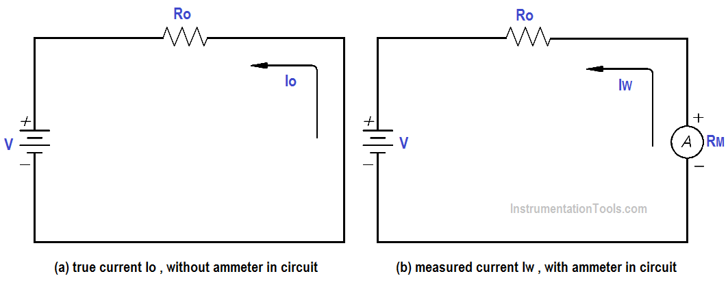
Ammeter

Figure 1 : Ammeter

When an ammeter is placed in series with a circuit, it will increase the resistance of that circuit by an amount equal to the internal resistance of the meter Rm.

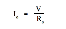
The below Equation is the mathematical representation of the current without the meter installed.

Ammeter Current Formula

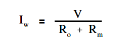
The below Equation is the mathematical representation of the current with the meter installed in the circuit.

Ammeter Current Formula - 1

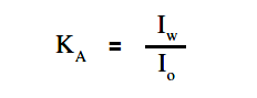
The accuracy of the ammeter KA is the ratio of the current when the meter is in the circuit, Iw , to the current with the meter out of the circuit, Io .

The below Equation is the mathematical representation for solving for the accuracy of the ammeter (KA).

accuracy of the ammeter

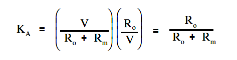
By substitution laws, The below Equation is a mathematical representation of the accuracy using circuit resistance.

Ammeter Accuracy Formula

The percent loading error is that percent of error due to loading effects that result from the added resistance of the meter.

The below Equation is a mathematical representation of the percent loading error.

% loading error = (1 – KA )(100 %)

A second error which occurs in an ammeter is calibration error. Calibration error is an error that occurs due to inaccurately marked meter faces. Typical values of calibration error in terms of full scale current are about 3 percent.

Example:

An ammeter, with a 10 mA full scale deflection and an internal resistance of 400 Ω, is placed in a circuit with a 20 V power source and a 2KΩ resistor.

Ammeter Accuracy Calculation

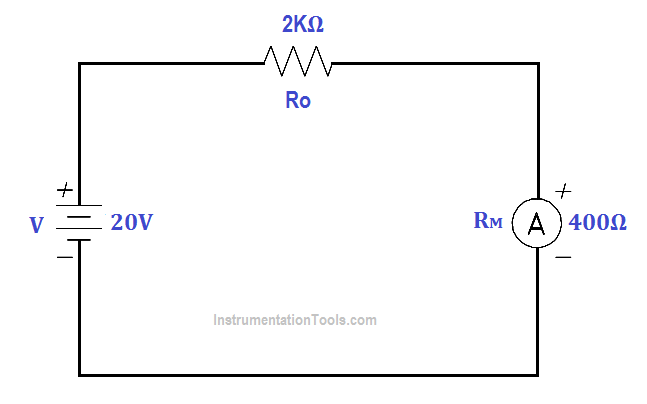
Figure 2 : Ammeter Accuracy

Find:

  1. accuracy
  2. %loading error
  3. true current
  4. measured current

Calculate Accuracy

KA = R / (Ro + Rm)

KA = 2000/(2000 + 2000)

KA = 0.833 or 83.3%

Calculate %loading error

% loading error = (1 – KA )(100 %)

% loading error = (1 – 0.833) (100%)

% loading error = 16.7 %

Calculate true current

Ammeter Current Formula

Io = 20 / 2000

Io = 0.01 A or 10mA

Calculate measured current

Ammeter Current Formula - 1

Iw = 20 / (2000 + 400)

Iw = 8.33 mA

An ammeter with a full scale Im can be shunted with a resistor RSH in order to measure currents in excess of Im (as shown in Figure). The reason for shunting an ammeter is to extend the range of the ammeter and, thereby, measure currents higher than the original full scale value.

Ammeter with Shunt

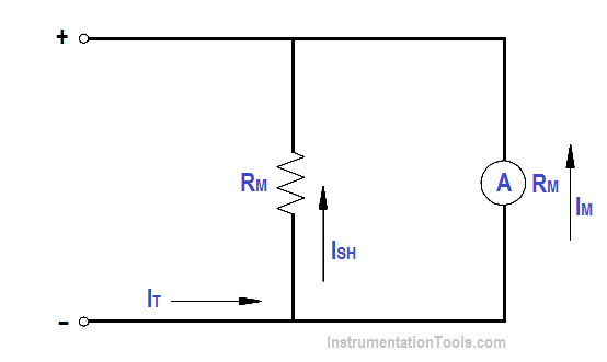
Figure 3 : Ammeter with Shunt

By Kirchhoff’s current law,
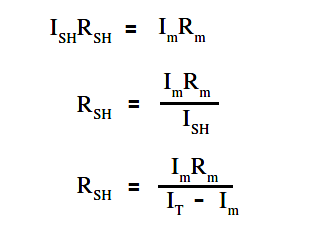
ISH = IT – Im

Since the voltage across the shunt must be equal to the voltage across the ammeter, shunt resistance is calculated as follows:

Ammeter Shunt Resistance

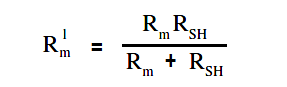
Therefore, the input resistance of a shunted ammeter is related to the meter and shunt resistance. The below Equation is a mathematical representation of this relationship.

NOTE: When computing accuracy for a shunted ammeter, use Rm‘ in place of Rm

Ammeter Current Formula - 2

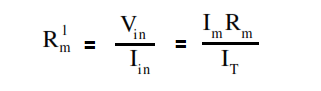
The below Equation is a mathematical representation of the relationship between input voltage and current to the ammeter and the value of input resistance.

Ammeter Current Formula - 3

Example:

An ammeter, with a 100 Ω meter resistance and a full scale deflection current of 4 mA, is to be shunted to measure currents from 1 to 20 mA.

Find:

  1. RSH
  2. Rm‘

Solution :

RSH = (Im Rm ) / ( Im – Rm )

RSH = 4 x 100 / (20-4)

RSH = 25Ω

Rm‘ = (Im Rm ) /  IT

Rm‘ = 4×100 / 20

Rm‘ = 20Ω

Don't Miss Our Updates
Be the first to get exclusive content straight to your email.
We promise not to spam you. You can unsubscribe at any time.
Invalid email address
You've successfully subscribed !
Magnetic Circuits
AC Induction Motor Slip
Y and Delta Resistor Network Calculations
Electrical Symbols
Synchronous Motors
Share This Article
Facebook Whatsapp Whatsapp LinkedIn Copy Link
Share
Leave a Comment

Leave a Reply Cancel reply

Your email address will not be published. Required fields are marked *

Stay Connected

128.3kFollowersLike
69.1kFollowersFollow
208kSubscribersSubscribe
38kFollowersFollow

Categories

Recent Comments

  • Kamli on Top Free PLC Software
  • Guifty Shimica on Top Non-PLC Certification Courses for Automation Professionals
  • Guifty Shimica on Top Non-PLC Certification Courses for Automation Professionals
  • MIHARITSOA Aina Sitraka on Top Non-PLC Certification Courses for Automation Professionals

Related Articles

Simple RC Circuit

Impedance in RC Circuits

Split Phase Motor

Single Phase AC Induction Motors

Parallel RLC Circuit

Resonance, Resonant Frequency, Series and Parallel Resonance

DC Machine

DC Machines Construction

4-Wire, Three-Phase Delta Wiring System

4-Wire, Three-Phase Delta Wiring System

Current in a Capacitor

Capacitance and Capacitive Reactance

Single Phase Motor Manual Controller

Motor Controllers

Voltage Drop in a Series Circuit

Series Resistance

More Articles

failure rate of a component - 1

Failure rate and MTBF of Safety Instrumented Systems

Rate Compensated Heat Detectors Working Principle

Rate Compensated Heat Detectors Working Principle

Solenoid Valve Functional Testing

Solenoid Valve Functional Testing

Fixed Type Motor control center (MCC)

Motor Control Center (MCC) Signal Interface Termination (SIT)

Electronics Mini Projects

300+ Best Electronics Mini Projects

Positive Feedback Principle

What is Feedback ?

Various Types of Sensors Used in Water Treatment Plant

Various Types of Sensors used in Water Treatment Plant

CODESYS HMI Interface

CODESYS HMI Interface

Follow US
All rights reserved. Reproduction in whole or in part without written permission is prohibited.
Welcome Back!

Sign in to your account

Username or Email Address
Password

Lost your password?