Inst ToolsInst ToolsInst Tools
  • Courses
  • Automation
    • PLC
    • Control System
    • Safety System
    • Communication
    • Fire & Gas System
  • Instrumentation
    • Design
    • Pressure
    • Temperature
    • Flow
    • Level
    • Vibration
    • Analyzer
    • Control Valve
    • Switch
    • Calibration
    • Erection & Commissioning
  • Interview
    • Instrumentation
    • Electrical
    • Electronics
    • Practical
  • Q&A
    • Instrumentation
    • Control System
    • Electrical
    • Electronics
    • Analog Electronics
    • Digital Electronics
    • Power Electronics
    • Microprocessor
  • Request
Search
  • Books
  • Software
  • Projects
  • Process
  • Tools
  • Basics
  • Formula
  • Power Plant
  • Root Cause Analysis
  • Electrical Basics
  • Animation
  • Standards
  • 4-20 mA Course
  • Siemens PLC Course
Reading: Classification of Transformers
Share
Font ResizerAa
Inst ToolsInst Tools
Font ResizerAa
  • Courses
  • Design
  • PLC
  • Interview
  • Control System
Search
  • Courses
  • Automation
    • PLC
    • Control System
    • Safety System
    • Communication
    • Fire & Gas System
  • Instrumentation
    • Design
    • Pressure
    • Temperature
    • Flow
    • Level
    • Vibration
    • Analyzer
    • Control Valve
    • Switch
    • Calibration
    • Erection & Commissioning
  • Interview
    • Instrumentation
    • Electrical
    • Electronics
    • Practical
  • Q&A
    • Instrumentation
    • Control System
    • Electrical
    • Electronics
    • Analog Electronics
    • Digital Electronics
    • Power Electronics
    • Microprocessor
  • Request
Follow US
All rights reserved. Reproduction in whole or in part without written permission is prohibited.
Inst Tools > Blog > Electrical Theory > Classification of Transformers

Classification of Transformers

Last updated: August 8, 2018 9:38 am
Editorial Staff
Electrical Theory
No Comments
Share
4 Min Read
SHARE

Transformers are constructed so that their characteristics match the application for which they are intended. The differences in construction may involve the size of the windings or the relationship between the primary and secondary windings. Transformer types are also designated by the function the transformer serves in a circuit, such as an isolation transformer.

Distribution Transformer

Distribution transformers are generally used in electrical power distribution and transmission systems. This class of transformer has the highest power, or volt-ampere ratings, and the highest continuous voltage rating. The power rating is normally determined by the type of cooling methods the transformer may use.

Some commonly-used methods of cooling are by using oil or some other heat-conducting material. Ampere rating is increased in a distribution transformer by increasing the size of the primary and secondary windings; voltage ratings are increased by increasing the voltage rating of the insulation used in making the transformer.

Power Transformer

Power transformers are used in electronic circuits and come in many different types and applications. Electronics or power transformers are sometimes considered to be those with ratings of 300 volt-amperes and below. These transformers normally provide power to the power supply of an electronic device, such as in power amplifiers in audio receivers.

Control Transformer

Control transformers are generally used in electronic circuits that require constant voltage or constant current with a low power or volt-amp rating. Various filtering devices, such as capacitors, are used to minimize the variations in the output. This results in a more constant voltage or current.

Auto Transformer

The auto transformer is generally used in low power applications where a variable voltage is required. The auto transformer is a special type of power transformer. It consists of only one winding. By tapping or connecting at certain points along the winding, different voltages can be obtained (as shown in Figure).

Auto Transformer Schematic

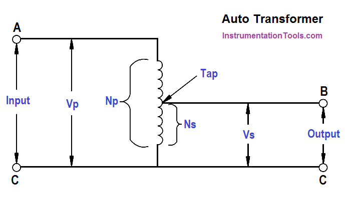
Figure : Auto Transformer Schematic

Isolation Transformer

Isolation transformers are normally low power transformers used to isolate noise from or to ground electronic circuits. Since a transformer cannot pass DC voltage from primary to secondary, any DC voltage (such as noise) cannot be passed, and the transformer acts to isolate this noise.

Potential Transformer

The potential transformer (PT) steps down voltage of a circuit to a low value that can be effectively and safely used for operation of instruments such as ammeters, voltmeters, watt meters, and relays used for various protective purposes.

Current Transformer

The current transformer (CT) steps down the current of a circuit to a lower value and is used in the same types of equipment as a potential transformer. This is done by constructing the secondary coil consisting of many turns of wire, around the primary coil, which contains only a few turns of wire. In this manner, measurements of high values of current can be obtained.

A current transformer should always be short-circuited when not connected to an external load. Because the magnetic circuit of a current transformer is designed for low magnetizing current when under load, this large increase in magnetizing current will build up a large flux in the magnetic circuit and cause the transformer to act as a step-up transformer, inducing an excessively high voltage in the secondary when under no load.

Don't Miss Our Updates
Be the first to get exclusive content straight to your email.
We promise not to spam you. You can unsubscribe at any time.
Invalid email address
You've successfully subscribed !

Continue Reading

DC Machines Construction
Schematic Diagram
Transformer Current Ratio
3-Wire, Three-Phase Delta Wiring System
Motor Controllers
Rectifiers, Forward Bias and Reverse Bias
Share This Article
Facebook Whatsapp Whatsapp LinkedIn Copy Link
Share
Leave a Comment

Leave a Reply Cancel reply

Your email address will not be published. Required fields are marked *

Stay Connected

128.3kFollowersLike
69.1kFollowersFollow
210kSubscribersSubscribe
38kFollowersFollow

Categories

Explore More

Batteries Theory
Series Circuit
Capacitance
Generator Action in a Motor
AC Generator Theory
Transformer Efficiency
Batteries
Resistance in Parallel Circuits

Keep Learning

Battery Interview QuBattery Interview Question and Answersestion and Answers

Battery Terminology

Current in a Capacitor

Capacitance and Capacitive Reactance

Simple RC Circuit

Impedance in RC Circuits

Power Triangle

Apparent Power, True Power, Reactive Power & Total Power

Series Parallel Circuit Analysis

Series – Parallel Circuit Analysis

Three Phase AC Generators

Three Phase AC Generators

Calculate Power in Series RC Circuit

Calculate Power in Series RC Circuit

Parallel Circuit

Parallel Circuit

Learn More

Tuning a Liquid Level Process Control Loop - 1

Tuning a Liquid Level Process Control Loop

PLC control 4 machines with 1 button

CX-Programmer Tutorial: 1 Button To Activate 4 Different Machines

4-20 mA Conversion Formulas

Standard 4 to 20 mA Conversion Formula

Download Free Robotics Software

Step by Step Guidelines to Download Free Robotics Software

Lower Explosive Limit (LEL)

Lower Explosive Limit (LEL)

Purpose of End of Line (EOL) Resistor in Fire & Gas System ?

Why we use End of Line (EOL) Resistor in Fire and Gas System ?

DeMorgan's Theorems

DeMorgan’s Theorems using Ladder Diagram

Ozone analyzer principle

Ozone Analyzer Working Principle

Menu

  • About
  • Privacy Policy
  • Copyright

Quick Links

  • Learn PLC
  • Helping Hand
  • Part Time Job

YouTube Subscribe

Follow US
All rights reserved. Reproduction in whole or in part without written permission is prohibited.
Welcome Back!

Sign in to your account

Username or Email Address
Password

Lost your password?