Inst ToolsInst ToolsInst Tools
  • Ask
  • Courses
  • Videos
  • Q & A
    • Interview
      • Instrumentation
      • Electronics
      • Electrical
      • Practical Questions
    • MCQ
      • Instrumentation MCQ
      • Electrical MCQ
      • Electronics MCQ
      • Control Systems MCQ
      • Analog Electronics MCQ
      • Digital Electronics MCQ
      • Power Electronics MCQ
      • Microprocessor MCQ
      • Multiple Choice Questions
  • EE
    • Electronics
      • Electronics Q & A
      • Electronic Basics
      • Electronic Devices & Circuits
      • Electronics Animation
      • Digital Electronics
    • Electrical
      • Electrical Basics
      • Electrical Q & A
      • Power Electronics
      • Electrical Machines
      • Electrical Animation
      • Power Systems
      • Switchgear & Protection
      • Transmission & Distribution
  • Measure
    • Control Valves
    • Calibration
    • Temperature
    • Pressure
    • Flow
    • Level
    • Analyzers
    • Switches
    • Vibration
    • Solenoid Valve
  • Control
    • PLC Tutorials
    • Control Systems
    • Safety Instrumented System (SIS)
    • Communication
    • Fire & Gas System
  • More
    • Design
    • Tools
    • Animation
    • Basics
    • Formulas
    • Standards
    • TextBooks
    • Common
    • Software
    • Excel Tools
    • Erection & Commissioning
    • Process Fundamentals
    • Videos
    • Books
Search
All rights reserved. Reproduction in whole or in part without written permission is prohibited.
Reading: Inductor
Share
Notification Show More
Font ResizerAa
Inst ToolsInst Tools
Font ResizerAa
  • Courses
  • PLC Tutorials
  • Control Systems
Search
  • Ask
  • Courses
  • Videos
  • Q & A
    • Interview
    • MCQ
  • EE
    • Electronics
    • Electrical
  • Measure
    • Control Valves
    • Calibration
    • Temperature
    • Pressure
    • Flow
    • Level
    • Analyzers
    • Switches
    • Vibration
    • Solenoid Valve
  • Control
    • PLC Tutorials
    • Control Systems
    • Safety Instrumented System (SIS)
    • Communication
    • Fire & Gas System
  • More
    • Design
    • Tools
    • Animation
    • Basics
    • Formulas
    • Standards
    • TextBooks
    • Common
    • Software
    • Excel Tools
    • Erection & Commissioning
    • Process Fundamentals
    • Videos
    • Books
Follow US
All rights reserved. Reproduction in whole or in part without written permission is prohibited.
Inst Tools > Blog > Electrical Theory > Inductor

Inductor

Last updated: July 27, 2018 9:33 am
Editorial Staff
Electrical Theory
No Comments
Share
5 Min Read
SHARE

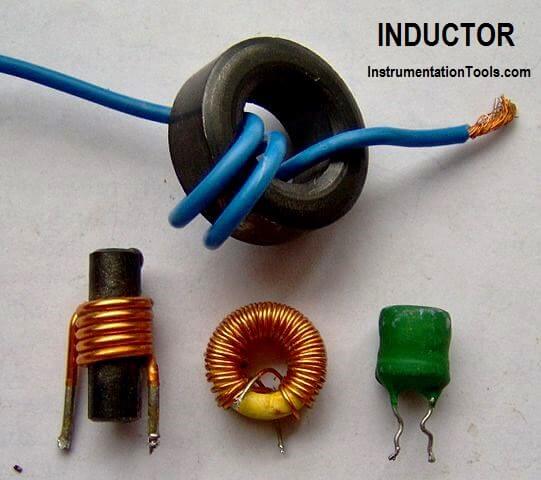
An inductor is a circuit element that will store electrical energy in the form of a magnetic field. It is usually a coil of wire wrapped around a core of permeable material. The magnetic field is generated when current is flowing through the wire.

Inductor Principle

If two circuits are arranged as in Figure 1, a magnetic field is generated around Wire A, but there is no electromotive force (EMF) induced into Wire B because there is no relative motion between the magnetic field and Wire B.

If we now open the switch, the current stops flowing in Wire A, and the magnetic field collapses. As the field collapses, it moves relative to Wire B. When this occurs, an EMF is induced in Wire B.

Magnetic Field Around Wire

Figure 1a : Magnetic Field Around a Wire Remains Constant

Magnetic Field Around Wire - 2

Figure 1b : Magnetic Field Around a Wire Collapsing

Figure 1 (a & b) : Induced EMF

This is an example of Faraday’s Law, which states that a voltage is induced in a conductor when that conductor is moved through a magnetic field, or when the magnetic field moves past the conductor. When the EMF is induced in Wire B, a current will flow whose magnetic field opposes the change in the magnetic field that produced it.

For this reason, an induced EMF is sometimes called counter EMF or CEMF. This is an example of Lenz’s Law, which states that the induced EMF opposes the EMF that caused it.

The three requirements for inducing an EMF are:

  1. a conductor,
  2. a magnetic field, and
  3. relative motion between the two.

Induced EMF in Coils

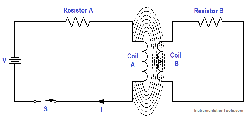
Figure 2 : Induced EMF in Coils

The faster the conductor moves, or the faster the magnetic field collapses or expands, the greater the induced EMF. The induction can also be increased by coiling the wire in either Circuit A or Circuit B, or both, as shown in Figure 2.

Self-induced EMF is another phenomenon of induction. The circuit shown in Figure 3 contains a coil of wire called an inductor (L). As current flows through the circuit, a large magnetic field is set up around the coil. Since the current is not changing, there is no EMF produced. If we open the switch, the field around the inductor collapses. This collapsing magnetic field produces a voltage in the coil. This is called self-induced EMF.

Self-Induced EMF

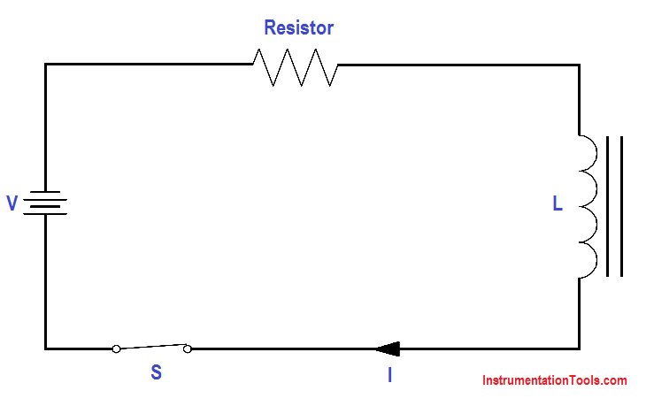
Figure 3 : Self-Induced EMF

The polarity of self-induced EMF is given to us by Lenz’s Law. The polarity is in the direction that opposes the change in the magnetic field that induced the EMF. The result is that the current caused by the induced EMF tends to maintain the same current that existed in the circuit before the switch was opened. It is commonly said that an inductor tends to oppose a change in current flow.

The induced EMF, or counter EMF, is proportional to the time rate of change of the current. The proportionality constant is called the “inductance” (L). Inductance is a measure of an inductor’s ability to induce CEMF. It is measured in henries (H). An inductor has an inductance of one henry if one amp per second change in current produces one volt of CEMF, as shown in below Equation.

Inductor Formula

where

CEMF = induced voltage (volts)
L = inductance (henries)
∆I/∆t = time rate of change of current (amp/sec)

The minus sign shows that the CEMF is opposite in polarity to the applied voltage.

Example:

A 4-henry inductor is in series with a variable resistor. The resistance is increased so that the current drops from 6 amps to 2 amps in 2 seconds. What is the CEMF induced?

Inductor Formula

CEMF = -4 {(2A-6A)/2}

CEMF = -4 x -2

CEMF = + 8 volts

Don't Miss Our Updates
Be the first to get exclusive content straight to your email.
We promise not to spam you. You can unsubscribe at any time.
Invalid email address
You've successfully subscribed !
Inductance and Inductive Reactance
Reading Electrical Schematics
Electrical Wiring Terminology
Series-Wound Motor
Rectifiers, Forward Bias and Reverse Bias
Share This Article
Facebook Whatsapp Whatsapp LinkedIn Copy Link
Share
Leave a Comment

Leave a Reply Cancel reply

Your email address will not be published. Required fields are marked *

Stay Connected

128.3kFollowersLike
69.1kFollowersFollow
208kSubscribersSubscribe
38kFollowersFollow

Categories

Recent Comments

  • Kamli on Top Free PLC Software
  • Guifty Shimica on Top Non-PLC Certification Courses for Automation Professionals
  • Guifty Shimica on Top Non-PLC Certification Courses for Automation Professionals
  • MIHARITSOA Aina Sitraka on Top Non-PLC Certification Courses for Automation Professionals

Related Articles

Units of Electrical Measurement

Units of Electrical Measurement

Motor Rotating Magnetic Field

AC Motor Theory

induction motor torque versus speed

Induction Motor Torque Versus Slip

3-Wire, Three-Phase Delta Wiring System

3-Wire, Three-Phase Delta Wiring System

Shunt-Wound DC Motor

Shunt-Wound Motor Operation

Electric Short Circuit

Series Short Circuit Faults

4-Wire, Three-Phase Delta Wiring System

4-Wire, Three-Phase Delta Wiring System

Three Phase To Single Phase Wiring Connections

Single Phase Power Wiring Schemes

More Articles

Strainer Principle

Backwashing

Drum Level differential pressure transmitter

Calculate Differential Pressure Sensed by Level Transmitter

Rotary Granulator Drive

Rotary Granulator Drive Root Cause Analysis (RCA)

Calibration of a Strain Gage Load Cell

Shunt Calibration of a Strain Gauge Load Cell

SIS Application Program - Safety Instrumented System

SIS Application Program – Safety Instrumented System

Electronic Devices & Circuits Objective Questions

Electronic Devices & Circuits Quiz – Set 5

PLC Important Questions and Answers

PLC Important Questions and Answers

PLC Cabinet

PLC Programming Videos

Follow US
All rights reserved. Reproduction in whole or in part without written permission is prohibited.
Welcome Back!

Sign in to your account

Username or Email Address
Password

Lost your password?