Inst ToolsInst ToolsInst Tools
  • Courses
  • Automation
    • PLC
    • Control System
    • Safety System
    • Communication
    • Fire & Gas System
  • Instrumentation
    • Design
    • Pressure
    • Temperature
    • Flow
    • Level
    • Vibration
    • Analyzer
    • Control Valve
    • Switch
    • Calibration
    • Erection & Commissioning
  • Interview
    • Instrumentation
    • Electrical
    • Electronics
    • Practical
  • Q&A
    • Instrumentation
    • Control System
    • Electrical
    • Electronics
    • Analog Electronics
    • Digital Electronics
    • Power Electronics
    • Microprocessor
  • Request
Search
  • Books
  • Software
  • Projects
  • Process
  • Tools
  • Basics
  • Formula
  • Power Plant
  • Root Cause Analysis
  • Electrical Basics
  • Animation
  • Standards
  • 4-20 mA Course
  • Siemens PLC Course
Reading: Parallel Tanks Level Control using PLC Ladder Diagram Tutorial
Share
Font ResizerAa
Inst ToolsInst Tools
Font ResizerAa
  • Courses
  • Design
  • PLC
  • Interview
  • Control System
Search
  • Courses
  • Automation
    • PLC
    • Control System
    • Safety System
    • Communication
    • Fire & Gas System
  • Instrumentation
    • Design
    • Pressure
    • Temperature
    • Flow
    • Level
    • Vibration
    • Analyzer
    • Control Valve
    • Switch
    • Calibration
    • Erection & Commissioning
  • Interview
    • Instrumentation
    • Electrical
    • Electronics
    • Practical
  • Q&A
    • Instrumentation
    • Control System
    • Electrical
    • Electronics
    • Analog Electronics
    • Digital Electronics
    • Power Electronics
    • Microprocessor
  • Request
Follow US
All rights reserved. Reproduction in whole or in part without written permission is prohibited.
Inst Tools > Blog > PLC Tutorials > Parallel Tanks Level Control using PLC Ladder Diagram Tutorial

Parallel Tanks Level Control using PLC Ladder Diagram Tutorial

This is a PLC Program to control the level of parallel tanks. Learn the PLC programming using this example.

Last updated: November 3, 2023 11:53 am
Editorial Staff
PLC Tutorials
3 Comments
Share
4 Min Read
SHARE

This is a PLC Program to control the level of parallel tanks. Learn the PLC programming using this example.

Contents
Parallel Tanks Level ControlProblem DiagramProblem SolutionList of Inputs & OutputsPLC Program for level control of parallel tanksProgram ExplanationResult

Parallel Tanks Level Control

Problem Description

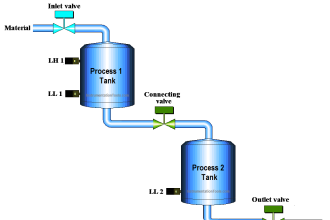
Two tanks are connected in parallel connection. We need to heat and cool the incoming material into the tanks and simultaneously control the level of the tanks.

Implement the PLC program for this application.

Problem Diagram
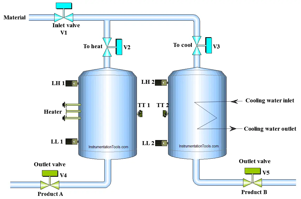
PLC Program to control level of parallel tanks

Problem Solution

Heating process is used to heat the material in the tank and cooling process is used to cool the material. Here consider both material are same as show in figure, inlet valve feeds material in both the tanks.

Here we can use level switches for detecting the low levels and high levels for both the tanks.

Use two temperature sensors for measuring the temperature of both the tanks.

Outlet valves are used at the bottom of the tanks to drain the materials for further process.

We will write PLC program for this application.

List of Inputs & Outputs

Digital Inputs

  • Cycle START :- I0.0
  • Cycle STOP :- I0.1
  • Low level tank 1(LL1) :- I0.3
  • Low level tank 2(LL2) :- I0.4
  • High level tank 1(LH1) :- I0.5
  • High level tank 2(LH2) :- I0.6

Digital Outputs

  • Inlet valve V2 for heating tank :- Q0.0
  • Inlet valve V3 for cooling tank :- Q0.1
  • Outlet valve V4 for heating tank :- Q0.2
  • Outlet valve V5 for cooling tank :- Q0.3

M memory

  • Cycle ON bit :- M0.0
  • Register for temperature of heating tank :- MD10
  • Register for temperature of cooling tank :- MD14
  • Outlet valve V5 for cooling tank :- Q0.3

PLC Program for level control of parallel tanks

Ladder diagram for the automatic level controlling of Parallel tanks
Parallel Tanks Level Control
PLC Parallel Tank
PLC Control Level
PLC Tank Level Diagram

Program Explanation

For this application we used S7-300 PLC and TIA portal software for programming. We can implement this logic by using other PLC also.

Network 1:

This Network is for latching circuit. Whenever START button is pressed (I0.0), Cycle ON (M0.0) bit will be ON. Cycle can be STOP by pressing STOP PB (I0.1).

Network 2:

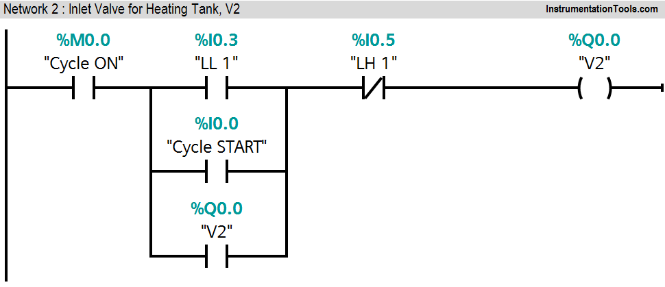
When heating tank level low (I0.3) is detected, inlet valve V2 (Q0.0) will be ON. If level high of tank 1(I0.5) is not detected and START (I0.0) button is pressed, inlet valve V2 (Q0.0) will be ON.

Network 3:

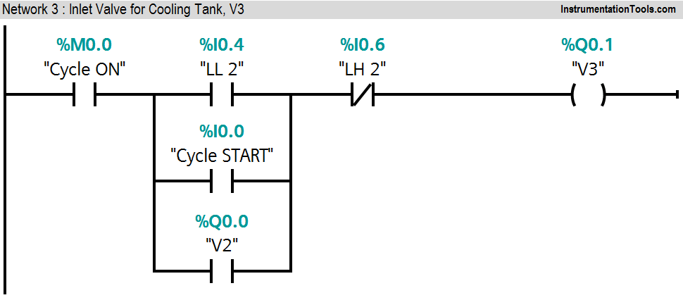
If level low of tank 2 (I0.4) is detected, inlet valve V3 (Q0.1) will be ON. If START button is pressed and high level of tank 2 (I0.6) is not detected, inlet valve V3 (Q0.1) will be ON.

Network 4:

If cycle is ON and actual temperature of heating tank (MD10) is greater or equal than set temperature (70°C), outlet valve V4 (Q0.2) will be ON

Network 5:

If cycle is ON and actual temperature of cooling tank (MD14) is less or equal than set temperature (20°C), outlet valve V5 (Q0.3) will be ON.

Note :- This example is only for explanation purpose only. We can implement this logic in any PLC or using relay logic. Above application may be different from actual application or may be a part of the plant logic.

Result

PLC Tank Programming

Author: Bhavesh

If you liked this article, then please subscribe to our YouTube Channel for PLC and SCADA video tutorials.

You can also follow us on Facebook and Twitter to receive daily updates.

Read Next:

  • Sequential Motor Control in PLC
  • PLC Program using Logic GATE
  • Alarm and Trip Documentation
  • Data Comparison PLC Instructions
  • What is a Seal-in Circuit?
Don't Miss Our Updates
Be the first to get exclusive content straight to your email.
We promise not to spam you. You can unsubscribe at any time.
Invalid email address
You've successfully subscribed !

Continue Reading

PLC Program for Artificial Fishpond Water Level Monitoring System
Free SCADA Training Course
Draw a Ladder Logic to switch ON-OFF a Bulb using a Toggle Switch ?
What is a PLC Retrofitting Project? – Importance, Procedure
How-to do Security of SCADA Systems?
Tia Portal – OB10 Time of Day Interrupt Organization Block
Share This Article
Facebook Whatsapp Whatsapp LinkedIn Copy Link
Share
3 Comments
  • Chaouch Mohamed Wael says:
    August 23, 2018 at 8:43 pm

    Thank you again for your efforts exerted in promoting education.

    Reply
  • swetha says:
    July 2, 2019 at 4:15 pm

    i want same process in scada.

    Reply
  • Jane Mabwai says:
    November 14, 2024 at 3:21 pm

    👍👍

    Reply

Leave a Reply Cancel reply

Your email address will not be published. Required fields are marked *

Stay Connected

128.3kFollowersLike
69.1kFollowersFollow
210kSubscribersSubscribe
38kFollowersFollow

Categories

Explore More

Single Loop Controller Questions
How to Use Symbol Factory Software for Graphic Design in HMI or SCADA?
What is Process Control?
Series Tanks Level Control using PLC Ladder Programming
Alarm Acknowledge using PLC
Communication Processor Module in Siemens PLC
Five Types of PLC Programming languages
PLC Program for Automatic Lamp Control in Storage Facility

Keep Learning

Loop Diagram

Documentation and Change Control of PLC or DCS Systems

PLC Controlling a Motor

PLC Motor Control Ladder Logic Programming

3 to 8 Line Decoder Circuit Diagram

3 to 8 Line Decoder PLC Ladder Diagram

Hardwired IO and Serial IO - Differences Explained

Hardwired I/O and Serial I/O – Differences Explained

PLC Example on Switch Program with Timers

PLC Example on Switch Program with Timers

SCADA Features

Features of SCADA

Trolley and hoist PLC control

PLC Crane Movement Control with Limit Switches

Industrial Automation Projects

Evaluating Industrial Automation Projects Return on investment (ROI)

Learn More

SFC Language in PLC Programming

SFC Language in PLC Programming

Electrical Simulator

Free Electrical Circuits Simulator Download

Thermocouple Software compensation

Thermocouple Software compensation

OSI Reference model

SCADA Communication and Protocols

Analyzer Sampling System

Gas Analyzer Sampling System

Programmable Logic Controller (PLC) Questions and Answers

Programmable Logic Controller (PLC) Questions and Answers – 5

What is Profinet

Profinet Communication – Specifications, Example, Advantages

Stilling wells

Stilling Wells for Level Measurement

Menu

  • About
  • Privacy Policy
  • Copyright

Quick Links

  • Learn PLC
  • Helping Hand
  • Part Time Job

YouTube Subscribe

Follow US
All rights reserved. Reproduction in whole or in part without written permission is prohibited.
Welcome Back!

Sign in to your account

Username or Email Address
Password

Lost your password?