Knowledge of key electrical terminology is necessary to fully understand principles in electrical theory.
The following are key terms:
- Conductor
- Insulator
- Resistor
- Electron current flow
- Conventional current flow
- Direct current (DC)
- Alternating current (AC)
- Ideal source
- Real source
Conductors
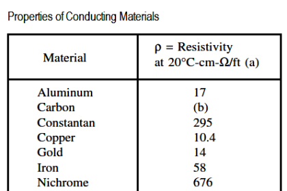
Conductors are materials with electrons that are loosely bound to their atoms, or materials that permit free motion of a large number of electrons. Atoms with only one valence electron, such as copper, silver, and gold, are examples of good conductors. Most metals are good conductors.
Insulators
Insulators, or nonconductors, are materials with electrons that are tightly bound to their atoms and require large amounts of energy to free them from the influence of the nucleus. The atoms of good insulators have their valence shells filled with eight electrons, which means they are more than half filled. Any energy applied to such an atom will be distributed among a relatively large number of electrons. Examples of insulators are rubber, plastics, glass, and dry wood.
Resistors
Resistors are made of materials that conduct electricity, but offer opposition to current flow. These types of materials are also called semiconductors because they are neither good conductors nor good insulators. Semiconductors have more than one or two electrons in their valence shells, but less than seven or eight. Examples of semiconductors are carbon, silicon, germanium, tin, and lead. Each has four valence electrons.
Voltage
The basic unit of measure for potential difference is the volt (symbol V), and, because the volt unit is used, potential difference is called voltage. An object’s electrical charge is determined by the number of electrons that the object has gained or lost. Because such a large number of electrons move, a unit called the “coulomb” is used to indicate the charge. One coulomb is equal to 6.28 x 10¹⁸ (billion, billion) electrons.
For example, if an object gains one coulomb of negative charge, it has gained 6,280,000,000,000,000,000 extra electrons. A volt is defined as a difference of potential causing one coulomb of current to do one joule of work. A volt is also defined as that amount of force required to force one ampere of current through one ohm of resistance. The latter is the definition with which we will be most concerned in this module.
Current
The density of the atoms in copper wire is such that the valence orbits of the individual atoms overlap, causing the electrons to move easily from one atom to the next. Free electrons can drift from one orbit to another in a random direction. When a potential difference is applied, the direction of their movement is controlled. The strength of the potential difference applied at each end of the wire determines how many electrons change from a random motion to a more directional path through the wire. The movement or flow of these electrons is called electron current flow or just current.
To produce current, the electrons must be moved by a potential difference. The symbol for current is (I). The basic measurement for current is the ampere (A). One ampere of current is defined as the movement of one coulomb of charge past any given point of a conductor during one second of time.
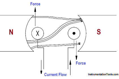
If a copper wire is placed between two charged objects that have a potential difference, all of the negatively-charged free electrons will feel a force pushing them from the negative charge to the positive charge. This force opposite to the conventional direction of the electrostatic lines of force is shown in Figure 9.
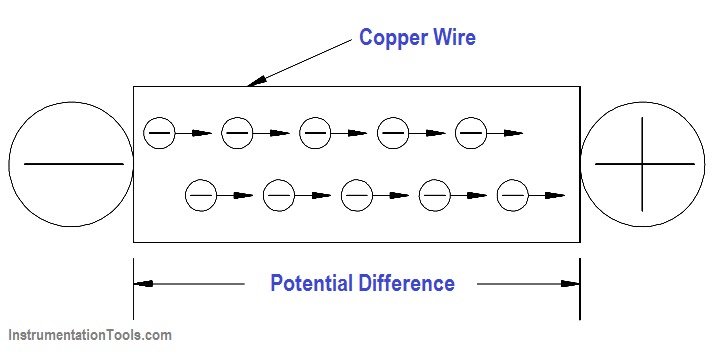
Figure 9 – Electron Flow Through a Copper Wire with a Potential Difference
The direction of electron flow, shown in Figure 10, is from the negative (-) side of the battery, through the wire, and back to the positive (+) side of the battery. The direction of electron flow is from a point of negative potential to a point of positive potential. The solid arrow shown in Figure 10 indicates the direction of electron flow. As electrons vacate their atoms during electron current flow, positively charged atoms (holes) result. The flow of electrons in one direction causes a flow of positive charges.
The direction of the positive charges is in the opposite direction of the electron flow. This flow of positive charges is known as conventional current and is shown in Figure 10 as a dashed arrow. All of the electrical effects of electron flow from negative to positive, or from a higher potential to a lower potential, are the same as those that would be created by a flow of positive charges in the opposite direction. Therefore, it is important to realize that both conventions are in use and that they are essentially equivalent; that is, all effects predicted are the same. In this text, we will be using electron flow in our discussions.
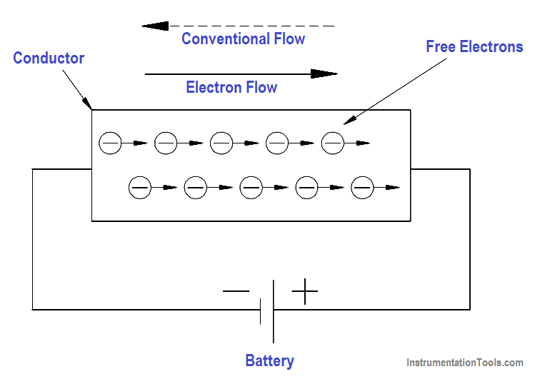
Figure 10 – Potential Difference Across a Conductor Causes a Current to Flow
Generally, electric current flow can be classified as one of two general types: Direct Current (DC) or Alternating Current (AC). A direct current flows continuously in the same direction. An alternating current periodically reverses direction. We will be studying DC and AC current in more detail later in this text.
An example of DC current is that current obtained from a battery. An example of AC current is common household current.
Real and Ideal Sources
An ideal source is a theoretical concept of an electric current or voltage supply (such as a battery) that has no losses and is a perfect voltage or current supply. Ideal sources are used for analytical purposes only since they cannot occur in nature.
A real source is a real life current or voltage supply that has some losses associated with it.
Summary
The important information contained in this article is summarized below.
- Conductor – material with electrons loosely bound to its atoms or that permits free motion of large number of electrons
- Insulator – material with electrons tightly bound to its atoms; requires large amounts of energy to free electrons from its nuclei
- Resistor – material that conducts electricity, but opposes current flow
- Electron Current Flow – current flow from negative to positive potentials
- Conventional Current Flow – current flow from positive to negative potentials
- Direct Current – current flow continuously in the same direction
- Alternating Current – current flow periodically reverses direction
- Ideal Source – theoretical current or voltage supply with no losses
- Real Source – actual current or voltage supply with losses