Inst ToolsInst ToolsInst Tools
  • Courses
  • Automation
    • PLC
    • Control System
    • Safety System
    • Communication
    • Fire & Gas System
  • Instrumentation
    • Design
    • Pressure
    • Temperature
    • Flow
    • Level
    • Vibration
    • Analyzer
    • Control Valve
    • Switch
    • Calibration
    • Erection & Commissioning
  • Interview
    • Instrumentation
    • Electrical
    • Electronics
    • Practical
  • Q&A
    • Instrumentation
    • Control System
    • Electrical
    • Electronics
    • Analog Electronics
    • Digital Electronics
    • Power Electronics
    • Microprocessor
  • Request
Search
  • Books
  • Software
  • Projects
  • Process
  • Tools
  • Basics
  • Formula
  • Power Plant
  • Root Cause Analysis
  • Electrical Basics
  • Animation
  • Standards
  • 4-20 mA Course
  • Siemens PLC Course
Reading: PLC Program for Alternate Output Circuit with Latched Function
Share
Font ResizerAa
Inst ToolsInst Tools
Font ResizerAa
  • Courses
  • Design
  • PLC
  • Interview
  • Control System
Search
  • Courses
  • Automation
    • PLC
    • Control System
    • Safety System
    • Communication
    • Fire & Gas System
  • Instrumentation
    • Design
    • Pressure
    • Temperature
    • Flow
    • Level
    • Vibration
    • Analyzer
    • Control Valve
    • Switch
    • Calibration
    • Erection & Commissioning
  • Interview
    • Instrumentation
    • Electrical
    • Electronics
    • Practical
  • Q&A
    • Instrumentation
    • Control System
    • Electrical
    • Electronics
    • Analog Electronics
    • Digital Electronics
    • Power Electronics
    • Microprocessor
  • Request
Follow US
All rights reserved. Reproduction in whole or in part without written permission is prohibited.
Inst Tools > Blog > Guest Articles > PLC Program for Alternate Output Circuit with Latched Function

PLC Program for Alternate Output Circuit with Latched Function

Design a PLC program for an alternate output circuit with a latched function and explain the ladder logic with a solution.

Last updated: November 3, 2023 11:38 am
Editorial Staff
Guest Articles PLC Tutorials
No Comments
Share
4 Min Read
SHARE

Design a PLC program for an alternate output circuit with a latched function and explain the ladder logic with a solution.

Contents
Alternate Output CircuitProblem DiagramProblem SolutionList of PLC Inputs & OutputsLadder Diagram for alternate output circuit (with latched function)PLC Program DescriptionTest Cases

Alternate Output Circuit

Problem Description

Setting the light ON by pressing a SWITCH on 1st time, 3rd time, 5th time etc. and setting the same light OFF by pressing the SWITCH by 2nd time , 4th time, 6th time etc.

Restore the output status to “0” when system or cycle power up. Output can be START by pressing a BUTTON in ODD number of times and can be STOP by pressing the same BUTTON by EVEN number of times.

Problem Diagram
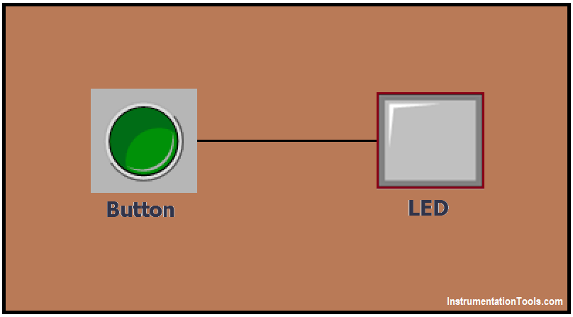
PLC Program for an Alternate output circuit

Problem Solution

We can solve this problem by using simple Ladder logic. In this we consider one simple example of alternate LED operation.

Here we consider one LED and one BUTTON. Press the BUTTON alternately and output should be ON/OFF alternately, here during the Button pressed odd number times then output should be ON and during the button pressing even number of times then the output should be OFF.

List of PLC Inputs & Outputs

Inputs List

  • SWITCH : I0.0

Output List

  • LED : Q0.0

M Memory

  • M0.0 for LED reset condition
  • M0.1 for counter reset
  • M11.0 & M11.1 – Positive edge

Ladder Diagram for alternate output circuit (with latched function)

circuit with latched function
PLC latched function
PLC Circuit Latched
PLC Switch Output
PLC Alternate Output

PLC Program Description

In this application, we have used Siemens S7-300 PLC and TIA Portal Software for programming.

Network 1:

In network 1 we have used SET instruction to set the LED (Q0.0). Here we have taken NO contact of BUTTON (I0.0)

so LED (Q0.0) can be activated by pressing BUTTON (I0.0).

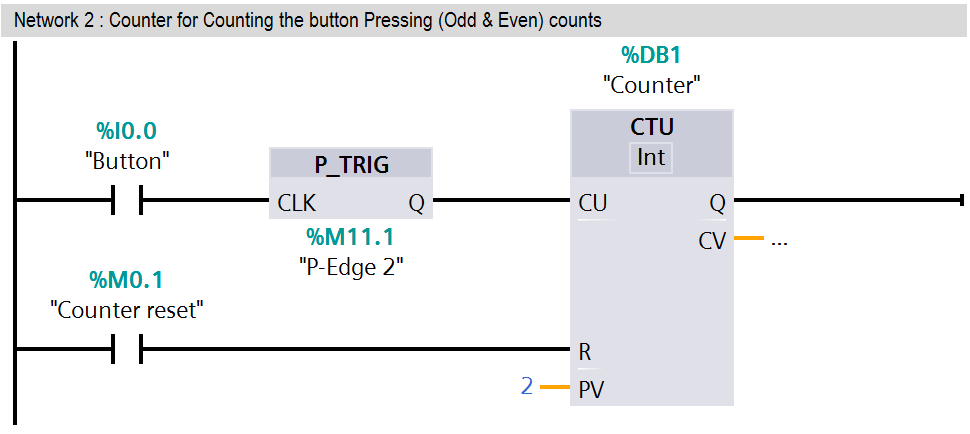
Network 2:

Here we used a counter so it will count the switching times of the BUTTON (I0.0).

This counter will tell us about the number of times the button is pressed, its value or the value is a EVEN number or ODD number.

Network 3:

When counter will reach its preset value (2) or say EVEN number of times, NO contact of the counter will set the M0.0 (LED reset condition).

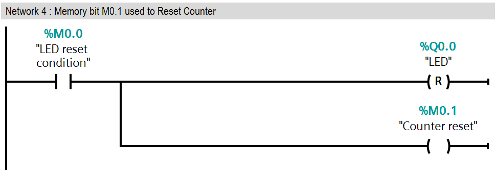
Network 4:

In this network NO contact of the M0.0 will RESET the LED and counter.

Here M0.1 (counter reset memory) will RESET the counter.

Network 5:

If M0.0 is ON and negative transition (from 1 to 0) of button (I0.0) will be triggered then RESET condition of LED will be OFF.

Note : This example is provided to understand the basic concept of alternate output circuit, it is not full application but we can use this concept in any automation application or any system.

Test Cases

alternate output circuit

Author : Bhavesh

If you liked this article, then please subscribe to our YouTube Channel for PLC and SCADA video tutorials.

You can also follow us on Facebook and Twitter to receive daily updates.

Read Next:

  • Setpoints and Alarms
  • PLC Digital Signals Wiring
  • Free SCADA Software 
  • PLC Contacts and coils
  • Control Room Interview Questions
Don't Miss Our Updates
Be the first to get exclusive content straight to your email.
We promise not to spam you. You can unsubscribe at any time.
Invalid email address
You've successfully subscribed !

Continue Reading

Tutorial: Siemens Communication between PLCs using I-Device
Automate Batch Mixing with Repeated Cycles in Omron PLC
Relay Operation, Types, Symbols & Characteristics
Two Hand Press Safety Control Circuit
5 Tips to Pass CFSE Exam
What Factors Affect the Choice of PLC Programming Software?
Share This Article
Facebook Whatsapp Whatsapp LinkedIn Copy Link
Share
Leave a Comment

Leave a Reply Cancel reply

Your email address will not be published. Required fields are marked *

Stay Connected

128.3kFollowersLike
69.1kFollowersFollow
210kSubscribersSubscribe
38kFollowersFollow

Categories

Explore More

How to Configure IP Address in Rockwell PLC?
PLC Structured Text Program for Light Sequences via Timers
What is Masking in PLC?
Features of Scada Which are Must in an IoT System
PLC Sequence Programming Ladder Logic
What is a PLC Retrofitting Project? – Importance, Procedure
PLC Programming: Sorting and Distribution of Boxes by Height
Flood Warning System using Programmable Logic Controller

Keep Learning

PLC project for traffic signals automation

Complete PLC Project: Traffic Light Auto and Manual Automation

PLC Tutorials - Timers and Counters

Difference between Timer and Counter – PLC Basics

PLC analog input scaling

PLC Analog Input Scaling

Allen Bradley PLC Example with Sub routines

How to use Sub Routines with Allen Bradley PLC

Ladder Logic for Stair-Case wiring using Toggle Switches

Ladder Logic for Stair-Case wiring using Toggle Switches

If Else Statement in SCL Language

If Else Statement in SCL Language

Select Security type Intouch

How to Add Security in InTouch SCADA?

PLC Ladder Program for Automatic Car Wash

PLC Ladder Program for Automatic Car Wash using Siemens TIA Portal

Learn More

HVDC transmission compared to HVAC transmission

Comparison of HVDC transmission and HVAC transmission

valve actuator yoke

Disassembly of Sliding-stem Control Valve

Modern Industrial Joystick Controls

Installing and Using Modern Industrial Joystick Controls

Total Resistance in a Parallel Circuit

Resistance in Parallel Circuits

Determine the Pressure at Each Port of DP Transmitter

Determine the Pressure at Each Port of DP Transmitter

SCADA Software and their Comparison

SCADA Software and their Comparison

Thermocouple Types

Types of Thermocouples

Closed-Tank-DP-Type-Level-Measurement-with-wet-leg-and-transmitter-installed-below-tapping-point

Level Measurement with Wet leg and Installed Below Tapping Point

Menu

  • About
  • Privacy Policy
  • Copyright

Quick Links

  • Learn PLC
  • Helping Hand
  • Part Time Job

YouTube Subscribe

Follow US
All rights reserved. Reproduction in whole or in part without written permission is prohibited.
Welcome Back!

Sign in to your account

Username or Email Address
Password

Lost your password?