Inst ToolsInst ToolsInst Tools
  • Courses
  • Videos
  • Q & A
    • Interview
      • Instrumentation
      • Electronics
      • Electrical
      • Practical Questions
    • MCQ
      • Instrumentation MCQ
      • Electrical MCQ
      • Electronics MCQ
      • Control Systems MCQ
      • Analog Electronics MCQ
      • Digital Electronics MCQ
      • Power Electronics MCQ
      • Microprocessor MCQ
      • Multiple Choice Questions
  • EE
    • Electronics
      • Electronics Q & A
      • Electronic Basics
      • Electronic Devices & Circuits
      • Electronics Animation
      • Digital Electronics
    • Electrical
      • Electrical Basics
      • Electrical Q & A
      • Power Electronics
      • Electrical Machines
      • Electrical Animation
      • Power Systems
      • Switchgear & Protection
      • Transmission & Distribution
  • Measure
    • Control Valves
    • Calibration
    • Temperature
    • Pressure
    • Flow
    • Level
    • Analyzers
    • Switches
    • Vibration
    • Solenoid Valve
  • Control
    • PLC Tutorials
    • Control Systems
    • Safety Instrumented System (SIS)
    • Communication
    • Fire & Gas System
  • More
    • Design
    • Tools
    • Animation
    • Basics
    • Formulas
    • Standards
    • TextBooks
    • Common
    • Software
    • Excel Tools
    • Erection & Commissioning
    • Process Fundamentals
    • Videos
    • Books
Search
All rights reserved. Reproduction in whole or in part without written permission is prohibited.
Reading: Inductance Type Pressure Transducers Principle
Share
Notification Show More
Font ResizerAa
Inst ToolsInst Tools
Font ResizerAa
  • Courses
  • PLC Tutorials
  • Control Systems
Search
  • Courses
  • Videos
  • Q & A
    • Interview
    • MCQ
  • EE
    • Electronics
    • Electrical
  • Measure
    • Control Valves
    • Calibration
    • Temperature
    • Pressure
    • Flow
    • Level
    • Analyzers
    • Switches
    • Vibration
    • Solenoid Valve
  • Control
    • PLC Tutorials
    • Control Systems
    • Safety Instrumented System (SIS)
    • Communication
    • Fire & Gas System
  • More
    • Design
    • Tools
    • Animation
    • Basics
    • Formulas
    • Standards
    • TextBooks
    • Common
    • Software
    • Excel Tools
    • Erection & Commissioning
    • Process Fundamentals
    • Videos
    • Books
Follow US
All rights reserved. Reproduction in whole or in part without written permission is prohibited.
Inst Tools > Blog > Pressure Measurement > Inductance Type Pressure Transducers Principle

Inductance Type Pressure Transducers Principle

Last updated: May 24, 2018 7:04 am
Editorial Staff
Pressure Measurement
No Comments
Share
2 Min Read
SHARE

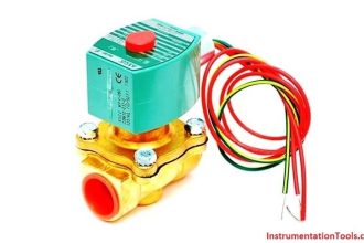
The inductance-type transducer consists of three parts: a coil, a movable magnetic core, and a pressure sensing element. The element is attached to the core, and, as pressure varies, the element causes the core to move inside the coil. An AC voltage is applied to the coil, and, as the core moves, the inductance of the coil changes. The current through the coil will increase as the inductance decreases. For increased sensitivity, the coil can be separated into two coils by utilizing a center tap, as shown in Figure 1. As the core moves within the coils, the inductance of one coil will increase, while the other will decrease.

Inductance-Type Pressure Transducer Coil

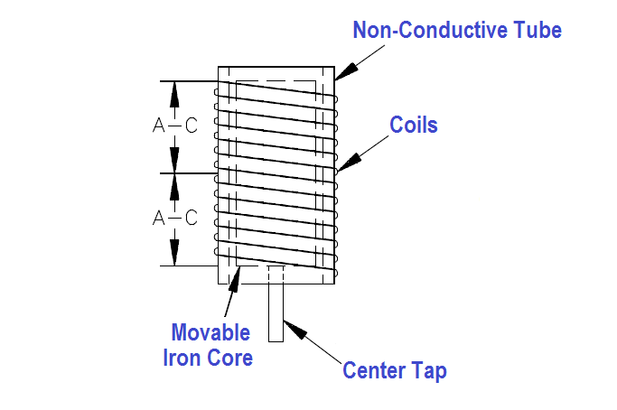
Figure 1 Inductance-Type Pressure Transducer Coil

Another type of inductance transducer, illustrated in Figure 2, utilizes two coils wound on a single tube and is commonly referred to as a Differential Transformer.

inductance transducer

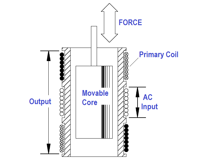
Figure 2 : Differential Transformer

The primary coil is wound around the center of the tube. The secondary coil is divided with one half wound around each end of the tube. Each end is wound in the opposite direction, which causes the voltages induced to oppose one another. A core, positioned by a pressure element, is movable within the tube. When the core is in the lower position, the lower half of the secondary coil provides the output. When the core is in the upper position, the upper half of the secondary coil provides the output. The magnitude and direction of the output depends on the amount the core is displaced from its center position. When the core is in the mid-position, there is no secondary output.

Don't Miss Our Updates
Be the first to get exclusive content straight to your email.
We promise not to spam you. You can unsubscribe at any time.
Invalid email address
You've successfully subscribed !

Recommended Articles

Helix and Spiral Tubes – Pressure Sensor
What is Capillary Tubing? – Advantages and Disadvantages
Pressure Measurement using Manometer
What is Hammer Effect in Gauges ?
Troubleshooting Fluid Systems Pressure Changes
Pressure Gauge Syphons Principle
Share This Article
Facebook Whatsapp Whatsapp LinkedIn Copy Link
Share
Leave a Comment

Leave a Reply Cancel reply

Your email address will not be published. Required fields are marked *

Stay Connected

128.3kFollowersLike
69.1kFollowersFollow
208kSubscribersSubscribe
38kFollowersFollow

Categories

Recent Comments

  • William Snyder on Top Non-PLC Certification Courses for Automation Professionals
  • Kamli on Top Free PLC Software
  • Guifty Shimica on Top Non-PLC Certification Courses for Automation Professionals
  • Guifty Shimica on Top Non-PLC Certification Courses for Automation Professionals

Related Articles

Yokogawa differential pressure transmitter

Basics of Differential Pressure Transmitters

Capacitive Pressure Transducer

Capacitive Type Pressure Transducers Principle

pressure-switch-calibration-procedure

Pressure Switch Calibration Procedure

Unbonded Strain Gauge Principle

Unbonded Strain Gauge Principle

Linear Variable Displacement Transducer (LVDT)

What is LVDT ?

Pressure Transmitters Filled impulse lines

Pressure Transmitters Filled impulse lines

Difference between Absolute, Gauge and Differential Pressure Transmitters

Difference between Absolute, Gauge and Differential Pressure Transmitters

Comparison of Pressure Instruments - Industrial Instrumentation

Comparison of Pressure Instruments – Industrial Instrumentation

More Articles

sinking-and-sourcing-digital-output-modules

PLC Digital Signals Wiring Techniques

Advantages and Disadvantages of Flow Measurement Techniques

Advantages & Disadvantages of Different Flow Meters

Simple PLC example Hardware configurations

Muting Functions of Safety Control Circuits – PLC Example

Alarm Trip for 24v DC Loop

Advantages & Disadvantages of Synchronous Motors

Immersion Electrical Heaters

Single and Three Phase Immersion Electrical Heaters Wiring Circuits

DP-Level-Transmitter-Open-tank-calibration

Open Tank DP Level Transmitter Calibration

Replace Failed Motors Quickly and Easily

Replace Failed Motors Quickly and Easily

Proof Testing of Safety Instrumented Systems

Proof Testing of Safety Instrumented Systems

Follow US
All rights reserved. Reproduction in whole or in part without written permission is prohibited.
Welcome Back!

Sign in to your account

Username or Email Address
Password

Lost your password?