Many traditional flow meter technologies respond to the volumetric flow rate of the moving fluid. Velocity-based flow meters such as magnetic, vortex, turbine, ultrasonic, and optical generate output signals proportional to the speed of fluid molecules and nothing else.
This means that if the fluid flowing through one of these flow meter types were to suddenly become denser (while still flowing by at the same number of volumetric units per minute), the flow meter’s response would not change at all.
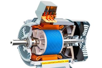
Flow Meters
The information provided by a volumetric flowmeter may not be what is actually best for the process being measured, however. If the flowmeter in question happens to be measuring the flow rate of feed into a chemical reactor vessel, for example, what we’re really concerned with is how many molecules per unit time of feed are entering that reactor, not how many cubic meters or how many gallons.
We know that changes in temperature will cause gases and liquids alike to change density, which means each volumetric unit will contain a different number of molecules after a temperature change than before.
Pressure has a similar influence on gases: increased pressure means more gas molecules occupying each cubic foot (or other volumetric unit), all other factors being equal. If a process requires an accounting of molecular flow rate, a volumetric flowmeter will not provide relevant information.
In steam boiler control systems, the flow rate of water into the boiler and the flow rate of steam coming out of the boiler must be matched in order to maintain a constant quantity of water within the boiler tubes and drums. However, water is a liquid and steam is a vapor, so flow measurements based on volume are meaningless: a cubic foot of steam will never contain the same number of molecules as a cubic foot of water.
The only reasonable way for the control system to balance both flow rates is to measure them as mass flows rather than volumetric flows. No matter what form (phase) the H2O molecules take, every kilogram going into the boiler must be matched by a kilogram coming out of the boiler in accordance with the Law of Mass Conservation: every H2O molecule entering the boiler must be matched by one H2O molecule exiting the boiler in order to maintain an unchanging quantity of H2O molecules within the boiler. This is why boiler feedwater and steam flowmeters alike are typically calibrated to measure in units of lbm (pounds mass) per unit time.
A similar problem arises in instances where the flowmeter is used for custody transfer. This term denotes scenarios where a particular material is being bought and sold, and where accuracy of flow measurement is a matter of monetary importance.
Again, in such instances, it is usually the number of molecules being bought and sold that really matters, not how many cubic meters or gallons those molecules occupy. Here, as with the chemical reactor feed flow application, a volumetric flowmeter does not provide the most relevant information.
We know from the study of chemistry that all elements have fixed mass values: one mole of any element in monatomic form (single, unbound atoms) will have a mass equal to the atomic mass of that element.
For example, one mole of carbon (C) atoms has a mass of 12 grams because the element carbon has an atomic mass of 12. Similarly, one mole of oxygen (O) atoms is guaranteed to have a mass of 16 grams because 16 is the atomic mass for the element oxygen. Consequently, one mole of carbon monoxide (CO) molecules will have a mass of 28 grams (12 + 16), and one mole of carbon dioxide (CO2) molecules will have a mass of 44 grams (12 + 16×2).
These molecule/mass relationships are fixed regardless of how dense or sparse the substances are: one mole of CO2 will have a mass of 44 grams regardless of pressure or temperature conditions affecting the density of that gas sample.
The relationship between molecule count and mass for any given chemical compound is fixed, because mass is an intrinsic property of matter. If our desire is to account for the number of molecules passed through a pipe, and we happen to know the chemical composition of those molecules, measuring the mass of the fluid passing through is the most practical way to do it.
The mathematical relationship between volumetric flow (Q) and mass flow (W) is one of proportionality with mass density (ρ):
W = ρQ
Dimensional analysis confirms this relationship. Volumetric flow is always measured in volume units (m3, ft3, cc, in3, gallons, etc.) over time, whereas mass flow is always measured in mass units (g, kg, lbm, or slugs) over time.
To use a specific example, a mass flow rate in pounds (mass) per minute will be obtained by multiplying a mass density in pounds per cubic foot by a volumetric flow rate in cubic feet per minute:
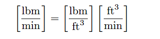
For example, a volumetric flow rate of 1000 cubic feet per minute of water is equivalent to 62400 pounds (mass) per minute, or 1040 lbm/s, with water having a density of 62.4 lbm/ft3.
Mass Flow Meters Technology
With modern sensing and computational technology, it is possible to combine pressure, temperature, and volumetric flow measurements in such a way to derive a measurement of mass flow.
This is precisely the goal with AGA3 flow measurement (orifice plates), AGA7 flow measurements (turbines), and AGA9 flow measurement (ultrasonic): “compensating” the fundamentally volumetric nature61 of these flow-measuring elements with pressure and temperature data to calculate the flow rate in mass units over time.
However, compensated flowmeter systems require much more calibration effort to maintain their long-term accuracy, not to mention a significant capital investment in the multiple transmitters and flow computer required to gather all the necessary data and perform the mass flow calculations.
It would be much simpler if there existed flowmeter technologies naturally responsive to the mass flow rate of a fluid! Fortunately, such flowmeter technologies do indeed exist, which is the subject of this section.
For each of the following mass flowmeter technologies, it should be clearly understood that the instrument in question naturally responds to mass flow rate.
To use our hypothetical example of a fluid stream whose density suddenly increases while the volumetric rate remains constant, a true mass flowmeter will immediately recognize the increase in mass flow (same volume rate, but more mass per unit volume) without the need for additional compensating measurements or computer calculations.
True mass flowmeters operate on principles directly related to the mass of the fluid molecules passing through the meter, making them fundamentally different from other flowmeter types.
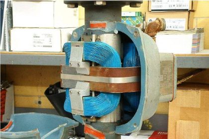
In the case of the Coriolis flowmeter, the instrument works on the principle of inertia: the force generated by an object when it is accelerated or decelerated. This basic property of mass (opposition to change in velocity) forms the basis of the Coriolis flowmeter’s function.
The inertial force generated inside a Coriolis flowmeter will thus double if the volumetric flowrate of a constant mass fluid doubles; the inertial force will likewise double if the density of a constant volumetric flow of fluid doubles. Either way, the inertial force becomes a representation of how fast mass is moving through the flowmeter, and so the Coriolis flowmeter is a true mass flow instrument.
In the case of the thermal flowmeter, the instrument works on the principle of convective heat transfer : heat energy extracted from a hot object as cooler molecules pass by. The ability for fluid molecules to transport heat is a function of the specific heat of each molecule and the number of molecules moving past the warmer object.
So long as the chemical composition of the fluid remains unchanged, the convective transfer of heat is a function of how many fluid molecules pass by in a given time. The heat transfer rate inside a thermal flowmeter will thus double if the volumetric flowrate of a given fluid doubles and all else remains constant; the heat transfer rate will likewise double if the density of a given fluid doubles and all else remains constant (i.e. twice the number of molecules passing by with each time interval).
Either way, the convective heat transfer rate becomes a representation of how many molecules of fluid are moving through the flowmeter, which for any given fluid type is proportional to the fluid’s mass flow rate. This makes the thermal flowmeter a true mass flow instrument for any (calibrated) fluid composition.
Some older, mechanical technologies exist for measuring true mass flow, but these are being supplanted by Coriolis and thermal mass flowmeter technologies. Coriolis and thermal mass flowmeters are also fast becoming the technology of choice for applications formerly the domain of compensated orifice plate (e.g. AGA3) and turbine (e.g. AGA7) flowmeters.
If you liked this article, then please subscribe to our YouTube Channel for Instrumentation, Electrical, PLC, and SCADA video tutorials.
You can also follow us on Facebook and Twitter to receive daily updates.
Read Next:
- Wedge Flow Meter Principle
- Flow Control Loop Analysis
- Coriolis Mass Flow Meter
- Oval Gear Flow Meter
- Displacement Flow meter