Inst ToolsInst ToolsInst Tools
  • Courses
  • Automation
    • PLC
    • Control System
    • Safety System
    • Communication
    • Fire & Gas System
  • Instrumentation
    • Design
    • Pressure
    • Temperature
    • Flow
    • Level
    • Vibration
    • Analyzer
    • Control Valve
    • Switch
    • Calibration
    • Erection & Commissioning
  • Interview
    • Instrumentation
    • Electrical
    • Electronics
    • Practical
  • Q&A
    • Instrumentation
    • Control System
    • Electrical
    • Electronics
    • Analog Electronics
    • Digital Electronics
    • Power Electronics
    • Microprocessor
  • Request
Search
  • Books
  • Software
  • Projects
  • Process
  • Tools
  • Basics
  • Formula
  • Power Plant
  • Root Cause Analysis
  • Electrical Basics
  • Animation
  • Standards
  • 4-20 mA Course
  • Siemens PLC Course
Reading: Filled-bulb Temperature Sensors
Share
Notification Show More
Font ResizerAa
Inst ToolsInst Tools
Font ResizerAa
  • Courses
  • Design
  • PLC
  • Interview
  • Control System
Search
  • Courses
  • Automation
    • PLC
    • Control System
    • Safety System
    • Communication
    • Fire & Gas System
  • Instrumentation
    • Design
    • Pressure
    • Temperature
    • Flow
    • Level
    • Vibration
    • Analyzer
    • Control Valve
    • Switch
    • Calibration
    • Erection & Commissioning
  • Interview
    • Instrumentation
    • Electrical
    • Electronics
    • Practical
  • Q&A
    • Instrumentation
    • Control System
    • Electrical
    • Electronics
    • Analog Electronics
    • Digital Electronics
    • Power Electronics
    • Microprocessor
  • Request
Follow US
All rights reserved. Reproduction in whole or in part without written permission is prohibited.
Inst Tools > Blog > Temperature Measurement > Filled-bulb Temperature Sensors

Filled-bulb Temperature Sensors

Last updated: June 24, 2019 7:27 am
Editorial Staff
Temperature Measurement
No Comments
Share
5 Min Read
SHARE

Filled-bulb systems exploit the principle of fluid expansion to measure temperature. If a fluid is enclosed in a sealed system and then heated, the molecules in that fluid will exert a greater pressure on the walls of the enclosing vessel.

By measuring this pressure, and/or by allowing the fluid to expand under constant pressure, we may infer the temperature of the fluid.

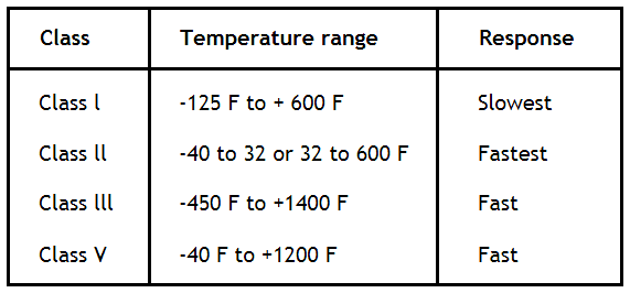
Four types of filled bulb temperature sensors

  1. Liquid Filled (Class I A,B)
  2. Vapor filled (Class II A,B,C,D)
  3. Gas Filled (Class III A,B)
  4. Mercury Filled (Class V A,B)

Filled-bulb Temperature Measurement Types

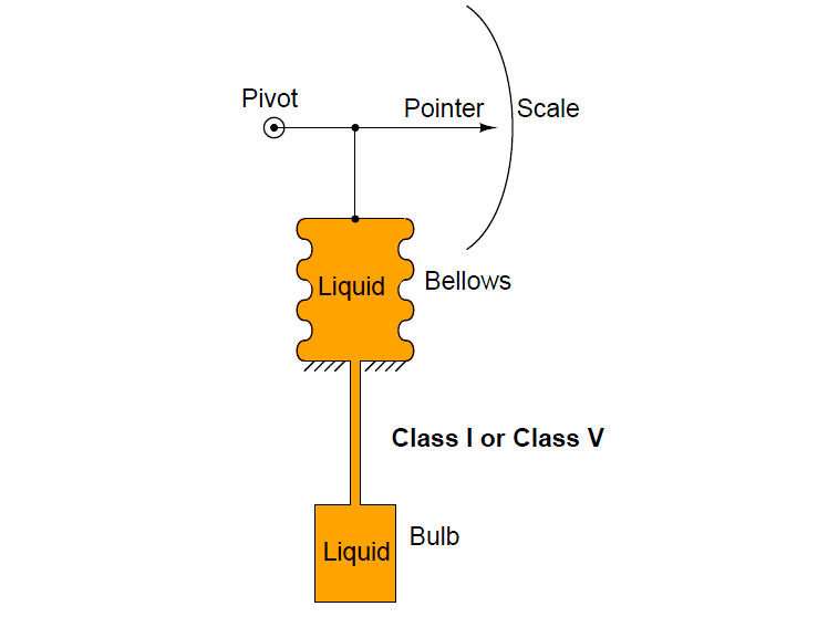
Class I and Class V systems use a liquid fill fluid (class V is mercury). Here, the volumetric expansion of the liquid drives an indicating mechanism to show temperature:

Filled-bulb Temperature Sensors

Class III systems use a gas fill fluid instead of liquid. Here, the change in pressure with temperature (as described by the Ideal Gas Law) allows us to sense the bulb’s temperature:

bulb’s temperature

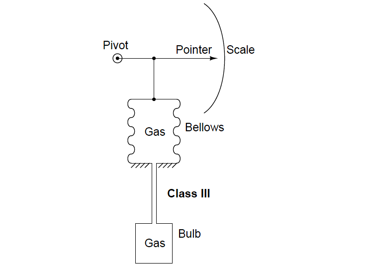
In these systems, it is quite critical that the tube connecting the sensing bulb to the indicating element be of minimal volume, so the fluid expansion is primarily due to changes in temperature at the bulb rather than changes in temperature along the length of the tube. It is also important to realize that the fluid volume contained by the bellows (or bourdon tube or diaphragm . . .) is also subject to expansion and contraction due to temperature changes at the indicator.

This means the temperature indication varies somewhat as the indicator temperature changes, which is not desirable, since we intend the device to measure temperature (exclusively) at the bulb.

Various methods of compensation exist for this effect (for example, a bi-metal spring inside the indicator mechanism to automatically offset the indication as ambient temperature changes), but it may be permanently offset through a simple “zero” adjustment provided that the ambient temperature at the indicator does not change much.

A fundamentally different class of filled-bulb system is the Class II, which uses a volatile liquid/vapor combination to generate a temperature-dependent fluid expansion:

Filled-bulb Temperature Measurement

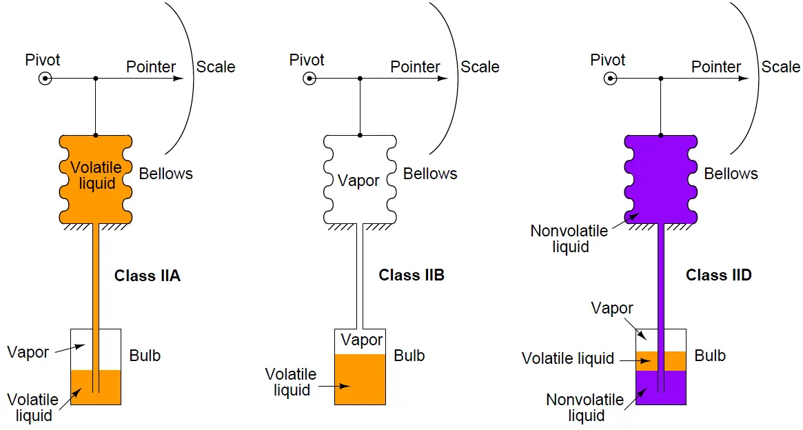
Given that the liquid and vapor are in direct contact with each other, the pressure in the system will be precisely equal to the saturated vapor pressure at the vapor/liquid interface.

This makes the Class II system sensitive to temperature only at the bulb and nowhere else along the system’s volume. Because of this phenomenon, a Class II filled-bulb system requires no compensation for temperature changes at the indicator.

Class II systems do have one notable idiosyncrasy, though: they have a tendency to switch from Class IIA to Class IIB when the temperature of the sensing bulb crosses the ambient temperature at the indicator.

Simply put, the liquid tends to seek the colder portion of a Class II system while the vapor tends to seek the warmer portion. This causes problems when the indicator and sensing bulb exchange identities as warmer/colder.

The rush of liquid up (or down) the capillary tubing as the system tries to reach a new equilibrium causes intermittent measurement errors. Class II filled-bulb systems designed to operate in either IIA or IIB mode are classified as IIC.

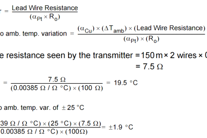
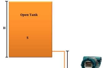
One calibration problem common to all systems with liquid-filled capillary tubes is an offset in temperature measurement due to hydrostatic pressure (or suction) resulting from a different in height between the measurement bulb and the indicator.

This represents a “zero” shift in calibration, which may be permanently offset by a “zero” adjustment at the time of installation. Class III (gas-filled) and Class IIB (vapor-filled) systems, of course, suffer no such problem because there is no liquid in the capillary tube to generate a pressure due to height.

Credits : Tony R. Kuphaldt – Creative Commons Attribution 4.0 License

Don't Miss Our Updates
Be the first to get exclusive content straight to your email.
We promise not to spam you. You can unsubscribe at any time.
Invalid email address
You've successfully subscribed !

Continue Reading

Thermowell Insertion and Immersion Length
Calibration of Pyrometers using Black Body
How 3 Wire RTD Lead Wire Resistance Eliminated?
Facts on Thermowell Insulation Thickness
Temperature Sensor Accessories
Thermocouple Properties, Temperature Ranges, Element Construction
Share This Article
Facebook Whatsapp Whatsapp LinkedIn Copy Link
Share
Leave a Comment

Leave a Reply Cancel reply

Your email address will not be published. Required fields are marked *

Stay Connected

128.3kFollowersLike
69.1kFollowersFollow
210kSubscribersSubscribe
38kFollowersFollow

Categories

Explore More

Types of Thermocouples
Difference Between 2 wire RTD, 3 wire RTD, and 4 wire RTD’s
Free Download Thermocouple Calculator
Why we use Wheatstone bridge in RTD?
How to calculate the tolerance of a RTD sensor
How to Convert 2 wire RTD into 3 or 4 wire RTD?
RTD Calibration
Thermocouples Sources of Error

Keep Learning

bimetallic thermometer working principle

Different Types of Thermometers

Thermocouple simulator

Problems of Reference Junction Compensation : Thermocouples

DTS sensors

Distributed Temperature Sensors (DTS) in Power Lines

Temperature Switch

Temperature Switch Working Principle

Electrical Resistance Temperature Curves of RTD

Resistance Temperature Detectors (RTD) Construction

General Specification of Thermowell

General Specification of Thermowell

PTC NTC Thermistors Comparation

Thermistor Working Principle

Three Wire RTD Wheatstone bridge Circuit

RTD Wheatstone Bridge Circuits

Learn More

process conditions, Find out the Circuit Components Status

As per Process Conditions, Find out the Circuit Components Status ?

What is a Dosing Pump? - Types, Advantages, Applications

What is a Dosing Pump? – Types, Advantages, Applications

3φ AC Power Connections

Three Phase Systems

Split-Range, Auto-Selector Ratio, And Cascade Systems

Split-Range, Auto-Selector, Ratio & Cascade Systems

Explain operation of the circuit

Explain Operation of the Lamp Circuit ?

Digital Electronics Multiple Choice Questions

Master-Slave Flip-Flops Objective Questions

Innovative Segment Orifice

Stuck Segment Orifice Dimensions Calculations

Celsius and Fahrenheit Temperature Values

What Temperature are Celsius and Fahrenheit Value Same ?

Menu

  • About
  • Privacy Policy
  • Copyright

Quick Links

  • Learn PLC
  • Helping Hand
  • Part Time Job

YouTube Subscribe

Follow US
All rights reserved. Reproduction in whole or in part without written permission is prohibited.
Welcome Back!

Sign in to your account

Username or Email Address
Password

Lost your password?