Inst ToolsInst ToolsInst Tools
  • Ask
  • Courses
  • Videos
  • Q & A
    • Interview
      • Instrumentation
      • Electronics
      • Electrical
      • Practical Questions
    • MCQ
      • Instrumentation MCQ
      • Electrical MCQ
      • Electronics MCQ
      • Control Systems MCQ
      • Analog Electronics MCQ
      • Digital Electronics MCQ
      • Power Electronics MCQ
      • Microprocessor MCQ
      • Multiple Choice Questions
  • EE
    • Electronics
      • Electronics Q & A
      • Electronic Basics
      • Electronic Devices & Circuits
      • Electronics Animation
      • Digital Electronics
    • Electrical
      • Electrical Basics
      • Electrical Q & A
      • Power Electronics
      • Electrical Machines
      • Electrical Animation
      • Power Systems
      • Switchgear & Protection
      • Transmission & Distribution
  • Measure
    • Control Valves
    • Calibration
    • Temperature
    • Pressure
    • Flow
    • Level
    • Analyzers
    • Switches
    • Vibration
    • Solenoid Valve
  • Control
    • PLC Tutorials
    • Control Systems
    • Safety Instrumented System (SIS)
    • Communication
    • Fire & Gas System
  • More
    • Design
    • Tools
    • Animation
    • Basics
    • Formulas
    • Standards
    • TextBooks
    • Common
    • Software
    • Excel Tools
    • Erection & Commissioning
    • Process Fundamentals
    • Videos
    • Books
Search
All rights reserved. Reproduction in whole or in part without written permission is prohibited.
Reading: Comparison of Transistor Configurations
Share
Notification Show More
Font ResizerAa
Inst ToolsInst Tools
Font ResizerAa
  • Courses
  • PLC Tutorials
  • Control Systems
Search
  • Ask
  • Courses
  • Videos
  • Q & A
    • Interview
    • MCQ
  • EE
    • Electronics
    • Electrical
  • Measure
    • Control Valves
    • Calibration
    • Temperature
    • Pressure
    • Flow
    • Level
    • Analyzers
    • Switches
    • Vibration
    • Solenoid Valve
  • Control
    • PLC Tutorials
    • Control Systems
    • Safety Instrumented System (SIS)
    • Communication
    • Fire & Gas System
  • More
    • Design
    • Tools
    • Animation
    • Basics
    • Formulas
    • Standards
    • TextBooks
    • Common
    • Software
    • Excel Tools
    • Erection & Commissioning
    • Process Fundamentals
    • Videos
    • Books
Follow US
All rights reserved. Reproduction in whole or in part without written permission is prohibited.
Inst Tools > Blog > Electronic Devices & Circuits > Comparison of Transistor Configurations

Comparison of Transistor Configurations

Last updated: September 27, 2016 3:25 pm
Editorial Staff
Electronic Devices & Circuits
No Comments
Share
3 Min Read
SHARE

There are three leads in a transistor viz., emitter, base and collector terminals.  However, when a transistor is to be connected in a circuit, we require four terminals; two for the input and two for the output.  This difficulty is overcome by making one terminal of the transistor common to both input and output terminals.  The input is fed between this common terminal and one of the other two terminals. The output is obtained between the common terminal and the remaining terminal. Accordingly; a transistor can be connected in a circuit in the following three ways :

(i)  common base connection

(ii) common emitter connection

(iii)  common collector connection

Each circuit connection has specific advantages and disadvantages.  It may be noted here that regardless of circuit connection, the emitter is always biased in the forward direction, while the collector always has a reverse bias.

Comparison of Transistor Connections

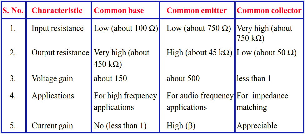
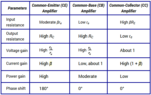
The comparison of various characteristics of the three connections is given below.

Comparison-of-transistors-configurations

Comparison of CB, CE & CC Amplifiers

Comparison of CB, CE & CC Amplifiers

(i)   CB Circuit

The input resistance (ri) of CB circuit is low because IE is high. The output resistance (ro) is high because of reverse voltage at the collector. It has no current gain (α < 1) but voltage gain can be high. The CB circuit is seldom used. The only advantage of CB circuit is that it provides good stability against increase in temperature.

(ii)  CE Circuit

The input resistance (ri) of a CE circuit is high because of small IB. Therefore, ri for a CE circuit is much higher than that of CB circuit. The output resistance (ro) of CE circuit is smaller than that of CB circuit. The current gain of CE circuit is large because IC is much larger than IB. The voltage gain of CE circuit is larger than that of CB circuit. The CE circuit is generally used because it has the best combination of voltage gain and current gain. The disadvantage of CE circuit is that the leakage current is amplified in the circuit, but bias stabilisation methods can be used.

(iii) CC Circuit

The input resistance (ri) and output resistance (ro) of CC circuit are respectively high and low as compared to other circuits. There is no voltage gain (Av < 1) in a CC circuit. This circuit is often used for impedance matching.
Don't Miss Our Updates
Be the first to get exclusive content straight to your email.
We promise not to spam you. You can unsubscribe at any time.
Invalid email address
You've successfully subscribed !
PMMC Temperature Compensation
Laser Diode Working Principle
Electronic Symbols
Transistor Voltage Divider Bias
What is Kirchhoff’s Voltage Law
Share This Article
Facebook Whatsapp Whatsapp LinkedIn Copy Link
Share
Leave a Comment

Leave a Reply Cancel reply

Your email address will not be published. Required fields are marked *

Stay Connected

128.3kFollowersLike
69.1kFollowersFollow
208kSubscribersSubscribe
38kFollowersFollow

Categories

Recent Comments

  • Kamli on Top Free PLC Software
  • Guifty Shimica on Top Non-PLC Certification Courses for Automation Professionals
  • Guifty Shimica on Top Non-PLC Certification Courses for Automation Professionals
  • MIHARITSOA Aina Sitraka on Top Non-PLC Certification Courses for Automation Professionals

Related Articles

What is a Filter Circuit

What is a Filter Circuit ?

phototransistor-circuit

Phototransistor Circuit Example

photo-diode

Photodiode Working Principle

Ideal Diode Characteristics Curve

Difference between ideal diode & conventional diode

Voltage Divider Rule

Voltage Divider Rule

diode-limiter-principle

Diode Limiters/Clippers Operation

Diode-vi-characteristic-curve-for-forward-bias

VI Characteristic of a Diode

Transistor-cut-off-saturation-active-regions

Transistor Cut off, Saturation & Active Regions

More Articles

Gauge Cock

Pressure Gauge Cocks

wedge Flow meter

What is a Segmental Wedge Flow Meter?

Electronic Devices & Circuits Objective Questions

Electronic Devices & Circuits Quiz – Set 1

DCS Troubleshooting Control Valve Loop

DCS Troubleshooting Control Valve Loop

Determine Calibration Range of Pneumatic Pressure Transmitter

Determine Calibration Range of Pneumatic Pressure Transmitter

Capacitive Level Measurement Principle

Capacitive Level Measurement

Instrument Heat Trace

Electrical Heat Tracing

Radiochemical Questions and Answers

Fundamentals of Radiochemical Methods Questions

Follow US
All rights reserved. Reproduction in whole or in part without written permission is prohibited.
Welcome Back!

Sign in to your account

Username or Email Address
Password

Lost your password?