Inst ToolsInst ToolsInst Tools
  • Courses
  • Videos
  • Q & A
    • Interview
      • Instrumentation
      • Electronics
      • Electrical
      • Practical Questions
    • MCQ
      • Instrumentation MCQ
      • Electrical MCQ
      • Electronics MCQ
      • Control Systems MCQ
      • Analog Electronics MCQ
      • Digital Electronics MCQ
      • Power Electronics MCQ
      • Microprocessor MCQ
      • Multiple Choice Questions
  • EE
    • Electronics
      • Electronics Q & A
      • Electronic Basics
      • Electronic Devices & Circuits
      • Electronics Animation
      • Digital Electronics
    • Electrical
      • Electrical Basics
      • Electrical Q & A
      • Power Electronics
      • Electrical Machines
      • Electrical Animation
      • Power Systems
      • Switchgear & Protection
      • Transmission & Distribution
  • Measure
    • Control Valves
    • Calibration
    • Temperature
    • Pressure
    • Flow
    • Level
    • Analyzers
    • Switches
    • Vibration
    • Solenoid Valve
  • Control
    • PLC Tutorials
    • Control Systems
    • Safety Instrumented System (SIS)
    • Communication
    • Fire & Gas System
  • More
    • Design
    • Tools
    • Animation
    • Basics
    • Formulas
    • Standards
    • TextBooks
    • Common
    • Software
    • Excel Tools
    • Erection & Commissioning
    • Process Fundamentals
    • Videos
    • Books
Search
All rights reserved. Reproduction in whole or in part without written permission is prohibited.
Notification Show More
Font ResizerAa
Inst ToolsInst Tools
Font ResizerAa
  • Courses
  • PLC Tutorials
  • Control Systems
Search
  • Courses
  • Videos
  • Q & A
    • Interview
    • MCQ
  • EE
    • Electronics
    • Electrical
  • Measure
    • Control Valves
    • Calibration
    • Temperature
    • Pressure
    • Flow
    • Level
    • Analyzers
    • Switches
    • Vibration
    • Solenoid Valve
  • Control
    • PLC Tutorials
    • Control Systems
    • Safety Instrumented System (SIS)
    • Communication
    • Fire & Gas System
  • More
    • Design
    • Tools
    • Animation
    • Basics
    • Formulas
    • Standards
    • TextBooks
    • Common
    • Software
    • Excel Tools
    • Erection & Commissioning
    • Process Fundamentals
    • Videos
    • Books
Follow US
All rights reserved. Reproduction in whole or in part without written permission is prohibited.
Inst Tools > Blog > Instrumentation Design > Pneumatic Valves and Cylinders Sizing – Part 1

Pneumatic Valves and Cylinders Sizing – Part 1

Last updated: May 10, 2019 12:56 pm
Editorial Staff
Instrumentation Design
No Comments
Share
7 Min Read
SHARE

Valve and cylinder sizing represents possibly the most important element in the design and specification of any pneumatic system. Carried out correctly, it will ensure that capital and operating costs are minimised, while maximising system performance, reliability and efficiency.

Contents
Cylinder SizingCylinder Thrust

Cylinder Sizing

Cylinder applications can be categorised as either:

  • STATIC, i.e. clamping, pressing, etc. or
  • DYNAMIC i.e. load moving.

In both cases the principle factors which must be considered when calculating the correct cylinder bore size are:

  • Amount of thrust required.
  • Available air pressure.
  • Efficiency of the cylinder

Cylinder Thrust

Cylinder thrust is a function of:

  • Piston diameter
  • Applied air pressure
  • Frictional resistance (efficiency

Required cylinder thrust is generally derived from a known clamping pressure (static) or the force required to move a particular load (dynamic) and is expressed in units of pounds force (lbf), kilogram force (kgf) or newtons (N).

In the case of dynamic applications, consideration must also be given to the decaying pressure on the side of the cylinder piston open to atmosphere.

Pneumatic Cylinder

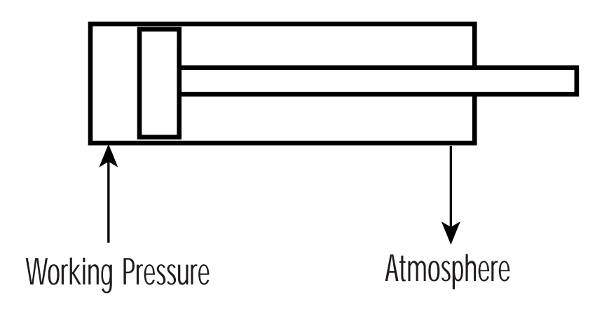
In order to regulate cylinder speed, the decaying pressure on the side of the cylinder’s piston open to atmosphere, should be approximately 1.5 bar and can be considered to work against the cylinder.

To determine the correct size of cylinder, it is necessary to use the formula:

Thrust = Pressure x Area x Efficiency

Pressure in this instance being the available air pressure, expressed in units of bar, N/m2, lbf/in2 or kgf/cm2, and area being the piston area in units of m2, cm2 or in2. (One bar equals approximately 1 kgf/cm2).

Cylinder efficiency varies between manufacturers, being dependent upon both cylinder construction and the seal technology employed. The general efficiency of cylinders designed with lip seals is considered to be 80% whilst more sophisticated and technologically advanced designs can be as high as 97%.

Example 1:

Determine the size of cylinder (D) required to move a load of 150 kg, given an air pressure of 7.3 bar (7.3 kgf/cm2 ). Assume an efficiency of 90%.

Thrust = Pressure x Area x Efficiency (μ)

therefore, 150 = (7.3 – 1.5) x (π D2 / 4) x 0.9

Transposing this formula then gives:

D2 = (150 x 4) / [(7.3 – 1.5) x p x 0.9]  = 36.6  = 6.05 cm

Note : The available pressure of 7.3 bar was reduced by 1.5 bar to allow for decaying pressure on the side of the piston open to atmosphere. The example uses on efficiency of 90%

The result is directly equivalent to the diameter of the cylinder required, measured in centimetres. In practice, however, cylinders with the exact calculated bore size are not usually available. It is therefore necessary to specify a cylinder with the next standard bore size. In this case, a 63mm cylinder would be selected.

Clearly, with a larger bore cylinder, a decrease in working pressure can be tolerated; the difference between available air pressure and required system working pressure being the maximum permissible system pressure drop.

The basic formula used above can also be developed to encompass the extending stroke on a single acting cylinder and the retracting stroke on a double acting device.

For the extending stroke on a single acting cylinder:

FE = P x A x μ – FS

Where:

FE represents the extending cylinder thrust

P = available pressure

A = piston area

μ = efficiency

FS = the spring force at the end of stroke

For the retracting stroke on a double acting cylinder:

FR = π(D2 – d2)/4 x P x μ

Where:

FR represents the cylinder thrust to retract

D = piston diameter

d = piston rod diameter

P = available pressure

μ = efficiency

Note : In this case, no allowance needs to be made for decaying pressure on the side of the piston open to atmosphere since when clamping, the piston will be static and this pressure will be zero.

Example 2:

Determine the size of a cylinder operating at a pressure of 6 bar (600000 N/m2), which would be capable of generating a clamping force of 1600N.

Based on the extending stroke formula:

Thrust = Pressure x Area x Efficiency (μ)

FE = P x πD2/4 x 0.9

therefore, 1600 = 600000 x πD2/4 x 0.9

Transposed to give:

D2 = (4 x 1600)/(600000 x π x 0.9)

D =  0.0614 m

D = 61.4 mm

Again, the next standard size of cylinder would be 63mm.

Once these formulae are understood, it is possible to produce a chart on which the theoretical thrust of any given cylinder bore can be shown against any given air pressure. See Figure below.

Cylinder Sizing

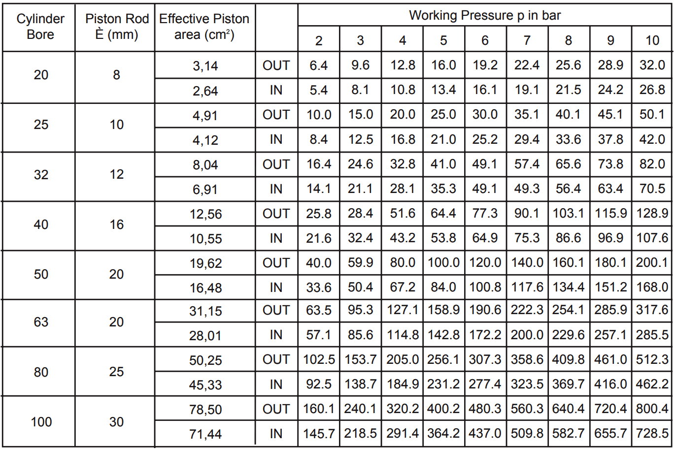
Note : If cylinder stroke is excessive and working pressure is near to maximum, final cylinder selection should be made in consultation with manufacturers representatives since rod buckling forces may need to be considered.

This chart does not take cylinder efficiency into consideration since this will vary between manufacturers. Values should, therefore, be multiplied by the efficiency factor to obtain usable thrust.

The graph below, Figure 2, allows an efficiency factor (m) to be obtained for various cylinder bore sizes where the supply pressure is known.

Pneumatic Cylinder Sizing

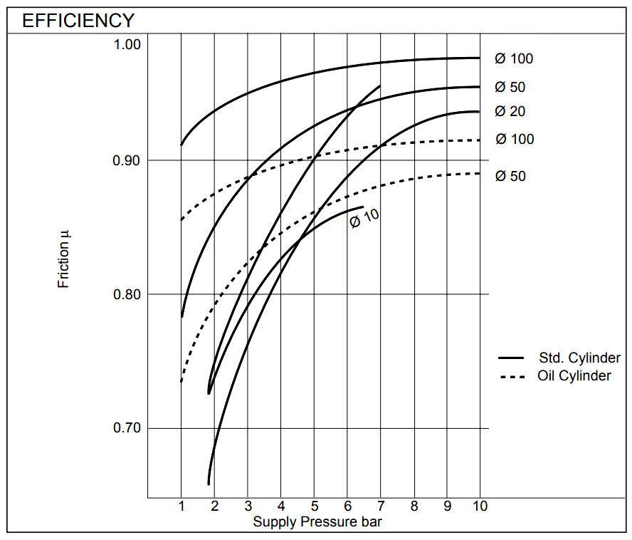
Note : The data shown on this graph applies to cylinders produced by SMC Pneumatics. Manufacturers of other cylinders should be consulted to obtain efficiencies for their designs.

Also Read : Pneumatic Valves and Cylinders Sizing – Part 2

Source : smc.eu

Don't Miss Our Updates
Be the first to get exclusive content straight to your email.
We promise not to spam you. You can unsubscribe at any time.
Invalid email address
You've successfully subscribed !

Continue Reading

How to Select a Directional Valves
Safety Roles & Responsibilities of Process Engineering (Detail Design)
Instrument Air Sizing
Vendor Document for Project Systems Architecture
Package Control and Safety Systems Implementation Methods
Pull Up and Pull Down Switch Circuits
Share This Article
Facebook Copy Link Print
Share
Leave a Comment

Leave a Reply Cancel reply

Your email address will not be published. Required fields are marked *

Stay Connected

128.3kFollowersLike
69.1kFollowersFollow
208kSubscribersSubscribe
38kFollowersFollow

Categories

Explore More

Motor Control Center (MCC) Signal Interface Termination (SIT)
Control Valve Recommended Practices for Harsh Process Conditions
DCS Controllers to Output Current Loops
Cut-outs between Platforms or Grating for Field Instruments
Process Control Systems Philosophy Concept
Basics of Cable Shields
What is Inter Discipline Check (IDC)?
How to Solve Cable Tray Sagging ?
Process Engineering Roles & Responsibilities – Design Company
Instrumentation Common Measurement Issues

Keep Learning

Instrument Loop Diagram

How-to Create Instrument Loop Diagram (ILD)?

Sample Schematic Template for Systems Architecture Diagram

Design Document for Project Systems Architecture

Steam Tracing

Steam Tracing

Multiple Thermowell Installations Problems

Multiple Thermowell Installations Problems

Immersion Electrical Heaters

Single and Three Phase Immersion Electrical Heaters Wiring Circuits

Electromechanical_Relays Circuit

Relay Loop Back Circuit

Poppet vs Spool Valves

Why Valve Type Matters ? Poppet vs Spool Valves

Insulation of Thermowell

Facts on Thermowell Insulation Thickness

Discover More

Saybolt Viscometer

Saybolt Viscometer

Basics of Motion Controllers

Basics of Motion Controllers

ISO 5167 Orifice Plate Types

Readers Questions on Flow Transmitter

Selection of Weighing Balance

Selection of Weighing Balance and Weight for Calibration

Ladder Logic for Stair-Case wiring using Toggle Switches

Ladder Logic for Stair-Case wiring using Toggle Switches

Erratic H2 Flow Rotameter

Erratic H2 Flow Rotameter

Power Electronics Objective Questions

Thyristor Family Quiz

Safety Control System

What is Safety Control System ?

Follow US
All rights reserved. Reproduction in whole or in part without written permission is prohibited.
Welcome Back!

Sign in to your account

Username or Email Address
Password

Lost your password?