Inst ToolsInst ToolsInst Tools
  • Courses
  • Automation
    • PLC
    • Control System
    • Safety System
    • Communication
    • Fire & Gas System
  • Instrumentation
    • Design
    • Pressure
    • Temperature
    • Flow
    • Level
    • Vibration
    • Analyzer
    • Control Valve
    • Switch
    • Calibration
    • Erection & Commissioning
  • Interview
    • Instrumentation
    • Electrical
    • Electronics
    • Practical
  • Q&A
    • Instrumentation
    • Control System
    • Electrical
    • Electronics
    • Analog Electronics
    • Digital Electronics
    • Power Electronics
    • Microprocessor
Search
  • Books
  • Software
  • Projects
  • Process
  • Tools
  • Basics
  • Formula
  • Power Plant
  • Root Cause Analysis
  • Electrical Basics
  • Animation
  • Standards
  • 4-20 mA Course
  • Siemens PLC Course
Reading: How to calculate Thermocouple Temperature by measuring the output millivoltage
Share
Notification Show More
Font ResizerAa
Inst ToolsInst Tools
Font ResizerAa
  • Courses
  • Design
  • PLC
  • Interview
  • Control System
Search
  • Courses
  • Automation
    • PLC
    • Control System
    • Safety System
    • Communication
    • Fire & Gas System
  • Instrumentation
    • Design
    • Pressure
    • Temperature
    • Flow
    • Level
    • Vibration
    • Analyzer
    • Control Valve
    • Switch
    • Calibration
    • Erection & Commissioning
  • Interview
    • Instrumentation
    • Electrical
    • Electronics
    • Practical
  • Q&A
    • Instrumentation
    • Control System
    • Electrical
    • Electronics
    • Analog Electronics
    • Digital Electronics
    • Power Electronics
    • Microprocessor
Follow US
All rights reserved. Reproduction in whole or in part without written permission is prohibited.
Inst Tools > Blog > Temperature Measurement > How to calculate Thermocouple Temperature by measuring the output millivoltage

How to calculate Thermocouple Temperature by measuring the output millivoltage

Last updated: December 10, 2019 4:17 pm
Editorial Staff
Temperature Measurement
6 Comments
Share
4 Min Read
SHARE

HOW TO DETERMINE TEMPERATURE BY MEASURING THE OUTPUT MILLIVOLTAGE OF A THERMOCOUPLE

THERMOCOUPLE REFERENCE TABLES

The N.I.S.T. (National Institute of Standards and Technology) is the U.S. standards setting agency. They have determined the output millivoltage of all type thermocouples, at all temperatures, within their range. The resulting tabulations are called “Thermocouple Reference Tables” and the thermocouple output millivoltage is shown for each degree of temperature.

Thermocouple Reference Tables

Type B Thermocouple    Download
Type R Thermocouple    Download
Type S Thermocouple    Download
Type T Thermocouple    Download
Type K Thermocouple    Download
Type C Thermocouple    Download

The junction of each type thermocouple produces a specific millivoltage across it at a specific temperature. A thermocouple consists of two junctions connected in opposition.

thermocouple formulas & Conversion
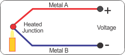
One is the measuring junction and the other is the reference junction. VD is the millivoltage resulting from the difference between the millivoltages generated by the two opposing junctions. VD is the millivoltage read when a meter is connected across the thermocouple as shown below.

HOW TO DETERMINE THE MEASURING JUNCTION TEMPERATURE

  1. Measure the “VD” millivoltage as shown above.
  2. Measure the actual temperature of the reference junction with a thermometer.
  3. Go to the table for the thermocouple being used and look up the millivoltage produced at that temperature.
  4. Add that millivoltage to the millivoltage measured as “VD” to get a total.
  5. Find that millivoltage total in the reference table. The corresponding temperature is the temperature of the measuring junction.

Example #1 Type “T” Thermocouple

Measured “VD” = 3.41 mV

Reference Junction Temperature = 22°C (71.6°F)

    1. From the table; 22°C = 0.87 mV.
    2. Adding 0.87 mV to 3.41 mV = 4.28 mV.
    3. Finding 4.28 mV In the table; the corresponding temperature is 100°C (212°F) and is the temperature of the measuring junction.

Example #2 Type “T” Thermocouple

Measured “VD” = 4.47 mV

Reference Junction Temperature = -5°C (23°F) (lower than the table reference of 0°C)

  1. From the table; 5°C = -0.193 mV
  2. Adding -0.193 mV to +4.47 mV = +4.28 mV
  3. Finding 4.28 mV In the table; the corresponding temperature is 100°C (212°F) and is the temperature of the measuring junction

Metric/English Scale Conversion °C = °F – 32 °F = 1.8°C + 32

Thermocouple Reference Chart

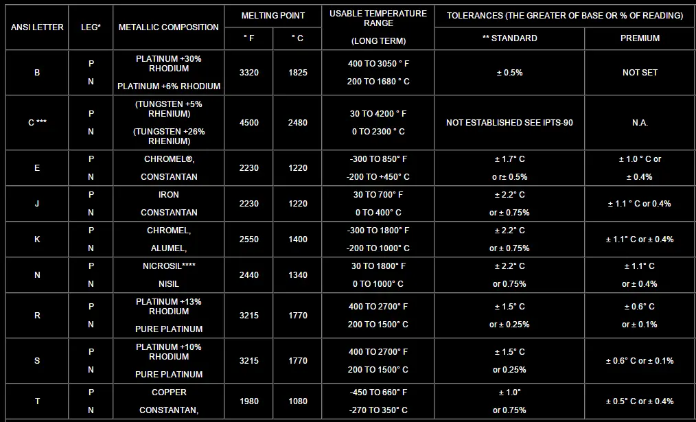
* P=Positive Leg N = Negative Leg

**”Standard” grade wire is sufficiently accurate for most applications. The purity and composition of “premium” grade wire is more closely controlled, and its millivoltage output is closer to the NIST standard chart and therefore reads somewhat more accurately than the “standard” grade does.

NOTE: Individual T/C units may be calibrated by measuring their output at several known temperatures and preparing an error correction chart. This chart is used to eliminate any deviation from the “standard” output millivoltage versus temperature readings inherent in this particular thermocouple. The result is known as an “NIST” traceable thermocouple.

Thermocouple chart
Thermocouple chart

Also Read: Basics 0f 4-20mA Current Signals

Don't Miss Our Updates
Be the first to get exclusive content straight to your email.
We promise not to spam you. You can unsubscribe at any time.
Invalid email address
You've successfully subscribed !

Continue Reading

Liquid In Glass Thermometer Principle
RTD Testing Methods in Calibration Laboratory
Bridge Circuit Construction
Important Factors for Thermocouple Selection
Temperature Switch Principle
Difference between PT100, PT1000, Nickel RTD and Balco RTD
Share This Article
Facebook Whatsapp Whatsapp LinkedIn Copy Link
Share
6 Comments
  • Eddy Stuyck says:
    January 14, 2017 at 11:57 am

    A more accurate but more complex way, is to use a real cold junction TC that is inserted in water of 0°C. This is water with melting ice in it. This gives a mV reading that equals the hot junction temperature.

    A little remark. Besides the American standard and tables, there are also German standards in use. Do not mix them since the values are different. Make sure which type of TC one is dealing with.

    Reply
  • Ramesh ketha says:
    July 25, 2017 at 7:11 pm

    Hi sir
    I am katha ramesh i asking about LBD ,card voltage 8 v,but when switch active 4.5v showing ,when switch normal voltage 7.5 v how generat 4.5v and 7.5v in LBD
    Please reply.

    Reply
  • tissa says:
    July 18, 2018 at 10:28 pm

    PT 100 3 wire
    calculate Thermocouple Temperature by measuring the output millivoltage
    measurement ,errors,working principle

    Reply
  • Sandeep says:
    December 10, 2019 at 4:42 pm

    Hi
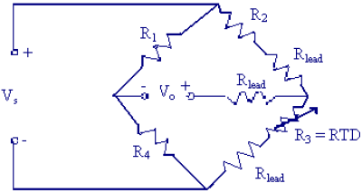
    Why using 3 and 4 wire in RTD ?
    What is the usage for this wires ?

    Reply
    • Vikas Ramchandra Pawar says:
      November 12, 2024 at 8:16 pm

      3 wire

      Reply
  • sreekanth says:
    December 21, 2023 at 9:43 pm

    In 2 and 3 wire RTD lead resistance added in 4 wire RTD no lead resistance so 4 wire RTD get accurate value

    Reply

Leave a Reply Cancel reply

Your email address will not be published. Required fields are marked *

Stay Connected

128.3kFollowersLike
69.1kFollowersFollow
210kSubscribersSubscribe
38kFollowersFollow

Categories

Explore More

Seebeck Effect Theory
Temperature Sensor Accessories
Basics of Temperature Switch
Foundation Fieldbus Temperature Transmitter Configuration
RTD Questions and Answers
Temperature Error of 2-Wire, 3-Wire & 4-Wire RTD
Thermowell Problems
Types of Thermocouples

Keep Learning

thermocouple types

What is a Thermocouple ?

Bi-metal Temperature Gauge

Bi-metal Temperature Sensors

Thermocouples Green Rot Effect

Thermocouples Green Rot Effect

Disadvantages of Resistance Temperature Detectors (RTD)

Disadvantages of Resistance Temperature Detectors

Optical Pyrometer

Optical Pyrometer Working Principle

RTD-standards

How to calculate the tolerance of a RTD sensor

Why have been limits imposed on the frequency ratio for thermowells?

Thermocouple Wiring Diagram

Basics of Thermocouples and RTD

Learn More

Modbus Vs DNP3

Difference between Modbus and DNP3 Communication Protocols

Power Electronics Objective Questions

Power Electronics Filter Quiz

Optical power loss testing

Fiber Optic Cable Testing

Contextual HMI

What is Contextual HMI? – HMI Screens on a Mobile or Tablet

Thermowell Shank to Flange Repeat Weld Leaks

Thermowell Shank to Flange Repeat Weld Leaks

Fire and Gas System

Types of Fire and Gas Detectors

Download Modscan software

How to Use ModScan Software for Testing Modbus Communication?

Electric Circuits Objective Questions

Electric Circuits Objective Questions – Set 10

Menu

  • About
  • Privacy Policy
  • Copyright

Quick Links

  • Learn PLC
  • Helping Hand
  • Part Time Job

YouTube Subscribe

Follow US
All rights reserved. Reproduction in whole or in part without written permission is prohibited.
Welcome Back!

Sign in to your account

Username or Email Address
Password

Lost your password?