Inst ToolsInst ToolsInst Tools
  • Courses
  • Automation
    • PLC
    • Control System
    • Safety System
    • Communication
    • Fire & Gas System
  • Instrumentation
    • Design
    • Pressure
    • Temperature
    • Flow
    • Level
    • Vibration
    • Analyzer
    • Control Valve
    • Switch
    • Calibration
    • Erection & Commissioning
  • Interview
    • Instrumentation
    • Electrical
    • Electronics
    • Practical
  • Q&A
    • Instrumentation
    • Control System
    • Electrical
    • Electronics
    • Analog Electronics
    • Digital Electronics
    • Power Electronics
    • Microprocessor
  • Request
Search
  • Books
  • Software
  • Projects
  • Process
  • Tools
  • Basics
  • Formula
  • Power Plant
  • Root Cause Analysis
  • Electrical Basics
  • Animation
  • Standards
  • 4-20 mA Course
  • Siemens PLC Course
Reading: As per Process Conditions, Find out the Circuit Components Status ?
Share
Notification Show More
Font ResizerAa
Inst ToolsInst Tools
Font ResizerAa
  • Courses
  • Design
  • PLC
  • Interview
  • Control System
Search
  • Courses
  • Automation
    • PLC
    • Control System
    • Safety System
    • Communication
    • Fire & Gas System
  • Instrumentation
    • Design
    • Pressure
    • Temperature
    • Flow
    • Level
    • Vibration
    • Analyzer
    • Control Valve
    • Switch
    • Calibration
    • Erection & Commissioning
  • Interview
    • Instrumentation
    • Electrical
    • Electronics
    • Practical
  • Q&A
    • Instrumentation
    • Control System
    • Electrical
    • Electronics
    • Analog Electronics
    • Digital Electronics
    • Power Electronics
    • Microprocessor
  • Request
Follow US
All rights reserved. Reproduction in whole or in part without written permission is prohibited.
Inst Tools > Blog > Instrumentation Design > As per Process Conditions, Find out the Circuit Components Status ?

As per Process Conditions, Find out the Circuit Components Status ?

Last updated: June 6, 2018 9:55 am
Editorial Staff
Instrumentation Design Practical Questions
8 Comments
Share
1 Min Read
SHARE

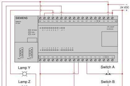
Determine the statuses of all lamps and relay coils in this circuit, given the following process conditions:

process conditions, Find out the Circuit Components Status

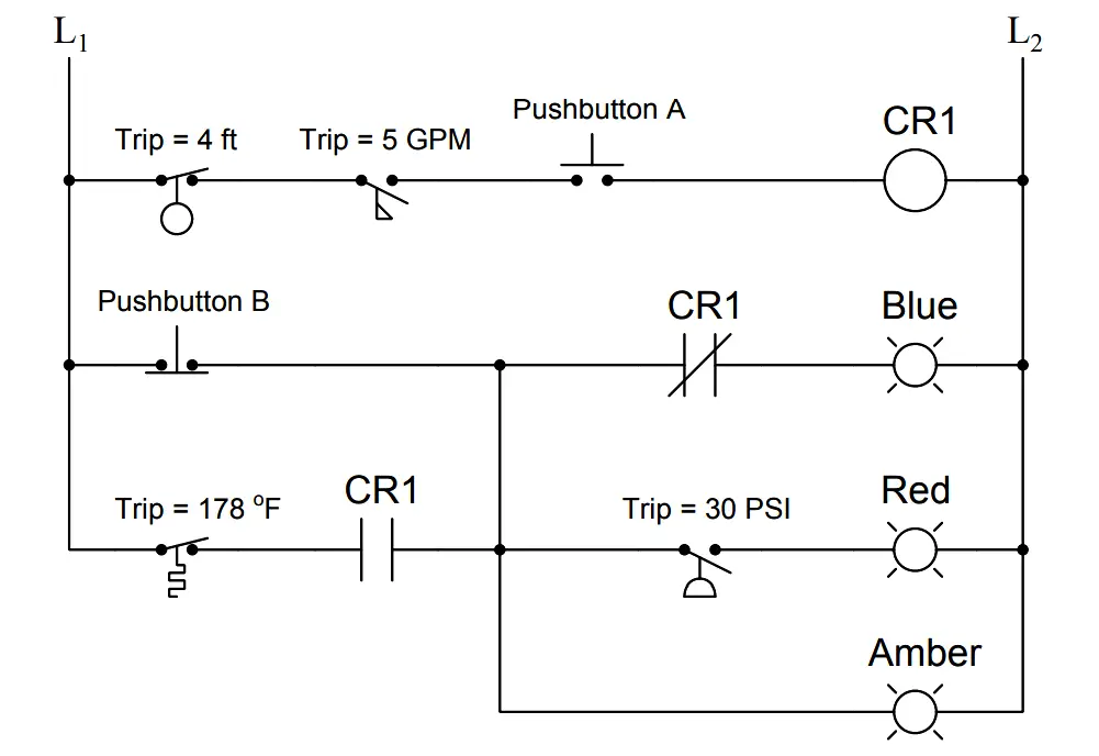
Process Conditions :

  • Flow = 7.9 GPM
  • Pressure = 36 PSI
  • Temperature = 210 Deg F
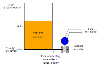
  • Level = 7.1 ft
  • Pushbutton A = pressed
  • Pushbutton B = unpressed

Answer :

Fully annotated circuit schematic: “X” representing an open contact or de-energized load, and “→” representing a closed contact or energized load.

process conditions, Find out the Circuit Components

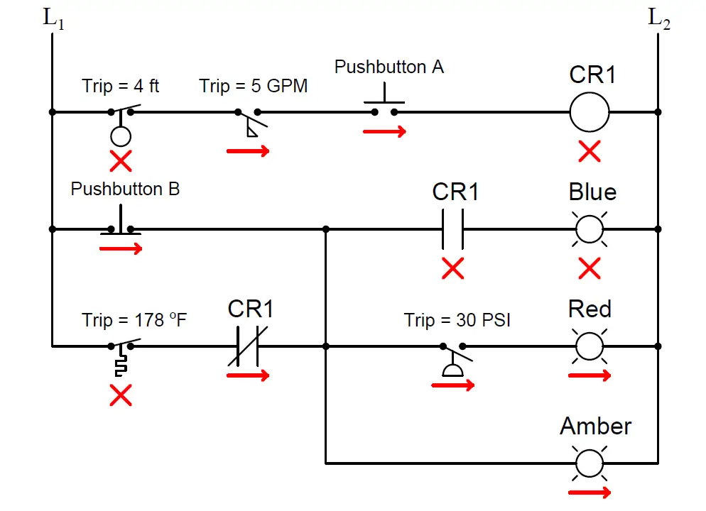
Recall that a process switch will be in its resting (“normal”) condition when the stimulus value is less than the trip threshold, and will be in its actuated condition when the stimulus exceeds the threshold.

Therefore,

  1. CR1 coil = de-energized
  2. Blue lamp = de-energized
  3. Red lamp = energized
  4. Amber lamp = energized

Share Your Answer / Comments

Credits : by Tony R. Kuphaldt – under CC BY 1.0

Don't Miss Our Updates
Be the first to get exclusive content straight to your email.
We promise not to spam you. You can unsubscribe at any time.
Invalid email address
You've successfully subscribed !

Continue Reading

Loop Powered Pressure Transmitter
Displacer Level Transmitter Questions
Differential Pressure Measurement across Baghouse
PLC Digital Signals Wiring Techniques
Remote Seal Transmitters Temperature Error
Practical Process Control System Questions & Answers – 5
Share This Article
Facebook Whatsapp Whatsapp LinkedIn Copy Link
Share
8 Comments
  • Sadok says:
    August 27, 2017 at 10:41 am

    Good presentation

    Reply
  • azetou says:
    August 31, 2017 at 8:58 am

    Hi, there is some issues with this exercise:

    First, you changed the program in the answer (Contact of CR1 is normally closed in the second rung and normally open in the third rung) the inverse what it is shown in the question.

    Second, If pushbutton B is unpressed than you are bypassing the Temprature switch and the CR1 contact.

    I think that a more logical program would be as you reported it in the answer with removing the connection between rung 3 and rung 2.

    Reply
    • S Bharadwaj Reddy says:
      August 31, 2017 at 10:30 am

      Hi, For easy understanding, There are some process conditions mentioned below the question, Apply the process conditions to the circuit diagram, so component status in the circuit will change accordingly then answer.

      Reply
  • azetou says:
    August 31, 2017 at 9:04 am

    it is a bit confusing, better to put programs that works in the real world.

    Reply
  • azetou says:
    August 31, 2017 at 9:30 am

    Just wondering , these answers are from Ton Kuphaldt or from you Mr Bharadwaj ???

    Reply
    • S Bharadwaj Reddy says:
      August 31, 2017 at 10:13 am

      by Mr. Tony R Kuphaldt

      Reply
      • azetou says:
        August 31, 2017 at 10:54 am

        Thank you.

        Reply
  • Akhil says:
    June 10, 2019 at 2:11 pm

    HI sir,

    First of all thank you sir for providing such a platform to study instrumentation. You are doing a great work.

    I have one doubt regarding the answer of these question.The ladder logic shown in the question has NC relay in the second rung and a NO relay in the third rung and they are in denergized state.

    After applying the process parameters to this ladder logic,it is observed that the CR1 coil is not energised,so then correspondingly the 2 relays are also not energised because they depend upon the coil CR1

    But in the answer it is shown that the relay state is changed,I think the ladder logic diagram shown in the question and answer are different.

    I think the answer will be,

    1.CR1 coil denergised
    2.Blue lamb energised
    3.Red lamb energised
    4.Amber lamb energised

    Awaiting your replay,
    Thank you sir.

    Reply

Leave a Reply Cancel reply

Your email address will not be published. Required fields are marked *

Stay Connected

128.3kFollowersLike
69.1kFollowersFollow
210kSubscribersSubscribe
38kFollowersFollow

Categories

Explore More

Detail Design Engineering Competency Aspects
How Earth Resistance is Measured
Why Strain Gauge Resistance Changes as it Stretches and Shrinks?
Instrumentation and Control (I&C) General Specifications
Instrumentation Bulk Material Requirements in Oxygen Service
Determine the Temperature of 3 Wire RTD
Industrial Automation Pre-Engineering Design Documents – Project & Process
Ferrules and Cross Ferruling

Keep Learning

Field Instruments Selection Aid

Field Instruments Selection Aid

Programmable Logic Controller (PLC) Questions and Answers – 9

Calculate Temperature of Four Wire RTD

Calculate the Temperature of 4 Wire RTD

PSV lift pressure

Calculate PSV Lift Pressure

Cable screen shall not be grounded

Cable Screen shall not be Grounded at Field Device ?

What Effect on Hydrostatic Level Transmitter if Liquid Density Changes?

What Effect on Hydrostatic Level Transmitter if Liquid Density Changes?

Float-type Level Switch for Sensing Low Oil Level

Float-type Level Switch for Sensing Low Oil Level

Process Switches Normal Status

Define Normal Status for each of the Process Switch

Learn More

Interface level Measurement

Interface Level Measurement using DP Transmitter

example-of-KCL

What is Kirchhoff’s Current Law

Inclined Water Manometer

How much Pressure is applied to Inclined Water Manometer?

Instrumentation Functional Diagrams Principle

Instrumentation Functional diagrams

Rotary Equipment

Modern Engineering Solutions for Rotary Equipment

SIS Fault Tolerance

SIS Hardware Fault Tolerance – Methods to Overcome HFT issues

Transmitter Performance and Calibration Frequency

How to Calculate Transmitter Performance and Calibration Frequency?

Problem on Water Filter Discharge Pressure Transmitter and Gauge

Problem on Water Filter Discharge Pressure Transmitter and Gauge

Menu

  • About
  • Privacy Policy
  • Copyright

Quick Links

  • Learn PLC
  • Helping Hand
  • Part Time Job

YouTube Subscribe

Follow US
All rights reserved. Reproduction in whole or in part without written permission is prohibited.
Welcome Back!

Sign in to your account

Username or Email Address
Password

Lost your password?