Inst ToolsInst ToolsInst Tools
  • Courses
  • Automation
    • PLC
    • Control System
    • Safety System
    • Communication
    • Fire & Gas System
  • Instrumentation
    • Design
    • Pressure
    • Temperature
    • Flow
    • Level
    • Vibration
    • Analyzer
    • Control Valve
    • Switch
    • Calibration
    • Erection & Commissioning
  • Interview
    • Instrumentation
    • Electrical
    • Electronics
    • Practical
  • Q&A
    • Instrumentation
    • Control System
    • Electrical
    • Electronics
    • Analog Electronics
    • Digital Electronics
    • Power Electronics
    • Microprocessor
  • Request
Search
  • Books
  • Software
  • Projects
  • Process
  • Tools
  • Basics
  • Formula
  • Power Plant
  • Root Cause Analysis
  • Electrical Basics
  • Animation
  • Standards
  • 4-20 mA Course
  • Siemens PLC Course
Reading: Determine the Status of Lamps and Relays in the Circuit ?
Share
Font ResizerAa
Inst ToolsInst Tools
Font ResizerAa
  • Courses
  • Design
  • PLC
  • Interview
  • Control System
Search
  • Courses
  • Automation
    • PLC
    • Control System
    • Safety System
    • Communication
    • Fire & Gas System
  • Instrumentation
    • Design
    • Pressure
    • Temperature
    • Flow
    • Level
    • Vibration
    • Analyzer
    • Control Valve
    • Switch
    • Calibration
    • Erection & Commissioning
  • Interview
    • Instrumentation
    • Electrical
    • Electronics
    • Practical
  • Q&A
    • Instrumentation
    • Control System
    • Electrical
    • Electronics
    • Analog Electronics
    • Digital Electronics
    • Power Electronics
    • Microprocessor
  • Request
Follow US
All rights reserved. Reproduction in whole or in part without written permission is prohibited.
Inst Tools > Blog > Practical Questions > Determine the Status of Lamps and Relays in the Circuit ?

Determine the Status of Lamps and Relays in the Circuit ?

Last updated: June 6, 2018 9:56 am
Editorial Staff
Practical Questions Instrumentation Design
No Comments
Share
1 Min Read
SHARE

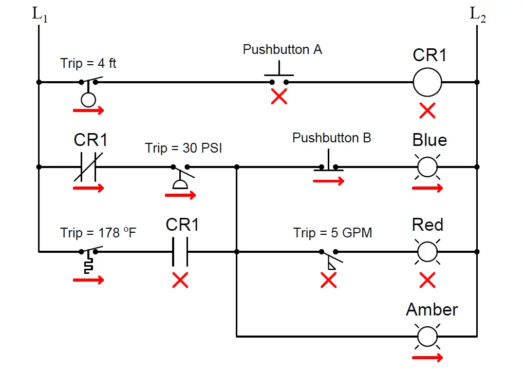
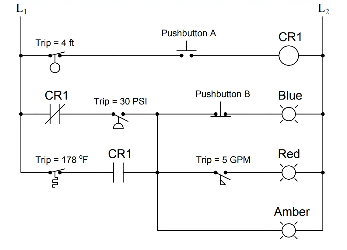
Determine the statuses of all lamps and relay coils in this circuit, given the following process conditions:

Determine the statuses of all lamps and relay coils in the circuit

Consider below mentioned Conditions :

  • Flow = 3.5 GPM
  • Pressure = 41 PSI
  • Temperature = 155 Deg F
  • Level = 1.3 ft
  • Pushbutton A = unpressed
  • Pushbutton B = unpressed

Answer :

Fully annotated circuit schematic: “X” representing an open contact or de-energized load, and “→” representing a closed contact or energized load.

Find the Circuit Lamps Status

Recall that a process switch will be in its resting (“normal”) condition when the stimulus value is less than the trip threshold, and will be in its actuated condition when the stimulus exceeds the threshold.

Therefore,

  1. CR1 coil = de-energized
  2. Blue lamp = energized
  3. Red lamp = de-energized
  4. Amber lamp = energized

Share Your Answer / Comments

Credits : by Tony R. Kuphaldt – under CC BY 1.0
Don't Miss Our Updates
Be the first to get exclusive content straight to your email.
We promise not to spam you. You can unsubscribe at any time.
Invalid email address
You've successfully subscribed !

Continue Reading

How to choose between PLC and DCS Systems ?
How to Minimize Water Vapor in Instrument Air Lines?
Air Compressor Control Circuit Problem
Pressure Transmitter using Potentiometer and Diaphragm
Thermowell Installation near Critical Equipment
Solenoid Valves Questions & Answers – 4
Share This Article
Facebook Whatsapp Whatsapp LinkedIn Copy Link
Share
Leave a Comment

Leave a Reply Cancel reply

Your email address will not be published. Required fields are marked *

Stay Connected

128.3kFollowersLike
69.1kFollowersFollow
210kSubscribersSubscribe
38kFollowersFollow

Categories

Explore More

Purpose of Loop Diagrams
Float-type Level Switch to Control a pump
Example PLC Program
Electronic Pressure Sensor with Bourdon Tube and LVDT
Instrument Air Compressor Control Philosophy
How-to Create Instrument Loop Diagram (ILD)?
Questions on Pneumatic Control Loop
How to Calculate Transmitter Performance and Calibration Frequency?

Keep Learning

Magnetic Flow Meters

Magnetic Flow Meters Installation Guidelines

Conductivity Meter

How to Select a Conductivity Meter

on off valve actuator

How to Select an Actuator for Valve

Problem on Tachogenerator

Problem on Tachogenerator

Alternative Vessel Level Indication

What is the Simple Alternative Vessel Level Indication?

Practical Process Control System Questions

Process Control Loop Testing

Programmable Logic Controller (PLC) Questions and Answers

Programmable Logic Controller (PLC) Questions and Answers – 7

Vendor Selection in Procurement Service Cycle (For Industrial Projects)

Compliance Table Application (for Procurement Service Cycle)

Learn More

Electrical Machines Questions and Answers

Transformer as a Magnetically Coupled Circuit

Interlock

Process Interlocks and Trips

PN Junction Questions & Answers

PN Junction Questions & Answers

Industrial Automation Acronyms

111 Industrial Automation Acronyms Questions and Answers

PLC Programmer Salary and Future Career Scope

PLC Programmer Salary and Future Career Scope

How to Run Multiple Motors with a Single VFD

How to Run Multiple Motors with a Single VFD?

Optocoupler Principle

Optocouplers Working Principle

Dome Valve Principle

Dome Valve Working Principle

Menu

  • About
  • Privacy Policy
  • Copyright

Quick Links

  • Learn PLC
  • Helping Hand
  • Part Time Job

YouTube Subscribe

Follow US
All rights reserved. Reproduction in whole or in part without written permission is prohibited.
Welcome Back!

Sign in to your account

Username or Email Address
Password

Lost your password?