Inst ToolsInst ToolsInst Tools
  • Courses
  • Automation
    • PLC
    • Control System
    • Safety System
    • Communication
    • Fire & Gas System
  • Instrumentation
    • Design
    • Pressure
    • Temperature
    • Flow
    • Level
    • Vibration
    • Analyzer
    • Control Valve
    • Switch
    • Calibration
    • Erection & Commissioning
  • Interview
    • Instrumentation
    • Electrical
    • Electronics
    • Practical
  • Q&A
    • Instrumentation
    • Control System
    • Electrical
    • Electronics
    • Analog Electronics
    • Digital Electronics
    • Power Electronics
    • Microprocessor
  • Request
Search
  • Books
  • Software
  • Projects
  • Process
  • Tools
  • Basics
  • Formula
  • Power Plant
  • Root Cause Analysis
  • Electrical Basics
  • Animation
  • Standards
  • 4-20 mA Course
  • Siemens PLC Course
Reading: OTDR Testing
Share
Notification Show More
Font ResizerAa
Inst ToolsInst Tools
Font ResizerAa
  • Courses
  • Design
  • PLC
  • Interview
  • Control System
Search
  • Courses
  • Automation
    • PLC
    • Control System
    • Safety System
    • Communication
    • Fire & Gas System
  • Instrumentation
    • Design
    • Pressure
    • Temperature
    • Flow
    • Level
    • Vibration
    • Analyzer
    • Control Valve
    • Switch
    • Calibration
    • Erection & Commissioning
  • Interview
    • Instrumentation
    • Electrical
    • Electronics
    • Practical
  • Q&A
    • Instrumentation
    • Control System
    • Electrical
    • Electronics
    • Analog Electronics
    • Digital Electronics
    • Power Electronics
    • Microprocessor
  • Request
Follow US
All rights reserved. Reproduction in whole or in part without written permission is prohibited.
Inst Tools > Blog > Communication > OTDR Testing

OTDR Testing

Last updated: April 15, 2018 5:46 pm
Editorial Staff
Communication eBooks
1 Comment
Share
5 Min Read
SHARE

An Optical Time-Domain Reflectometer or OTDR is a sophisticated test instrument used to probe the characteristics of long optical fibers. They work by injecting a very brief pulse of light into one end of a long optical fiber, then monitoring any light received at that same end of the fiber. As the light pulse travels down the length of the fiber, it continuously loses some of its magnitude due to scattering in the glass. Some of this scattered light returns back to the source-end of the fiber, presenting a sort of “continuous echo” of the moving pulse. This continuous echo is analogous to the noise heard from an object moving away from the listener. As the light pulse encounters flaws and other discontinuities in the fiber and/or connectors along its length, the echoed signal changes in magnitude. This received signal is displayed as a time-domain plot on the OTDR viewing screen, and will look something like this: Fiber under test “

OTDR testing

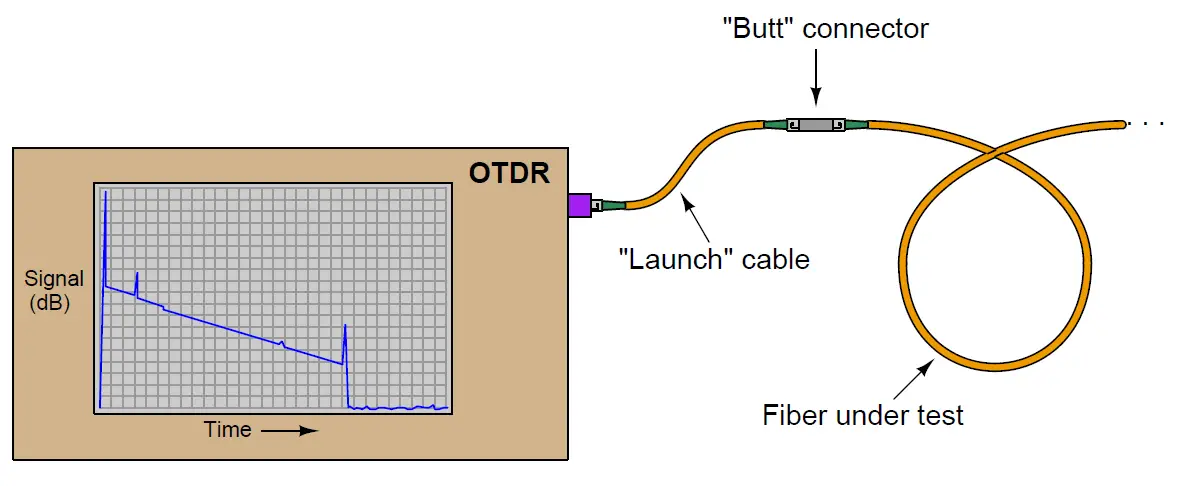
The “trace” shown on the display screen of an OTDR is a plot of the received optical signal strength over time. A large “spike” at the left-hand side of this trace marks the incident pulse of light injected into the optical fiber by the OTDR from the traveling pulse as it propagates down the length of the fiber. All signals after that (to the right of that initial “spike”) represent light received from that same end of the optical fiber. In a completely uniform fiber the resulting “echo” would trace a downward-sloping straight line as the traveling light pulse gradually weakens.

In an imperfect fiber, any discontinuities such as splices, connector joints, sharp bends, cracks, etc. will cause the traveling light pulse to lose more photons than usual at the location of the discontinuity: sometimes returning a strong echo back toward the OTDR and other times not. A discontinuity such as a mis-aligned fiber connector will tend to return a strong echo as part of the traveling light pulse reflects off the mis-aligned connector end and returns to the OTDR. A discontinuity such as a mal-formed fusion splice merely scatters a greater-than-normal amount of light out through the fiber’s cladding, in which case there is no echo “pulse” received by the OTDR but rather just a further weakening of the echo signal.

The OTDR trace shown in the previous illustration demands further explanation. Shown here is a magnified view of it, complete with numbers to identify each noteworthy event:
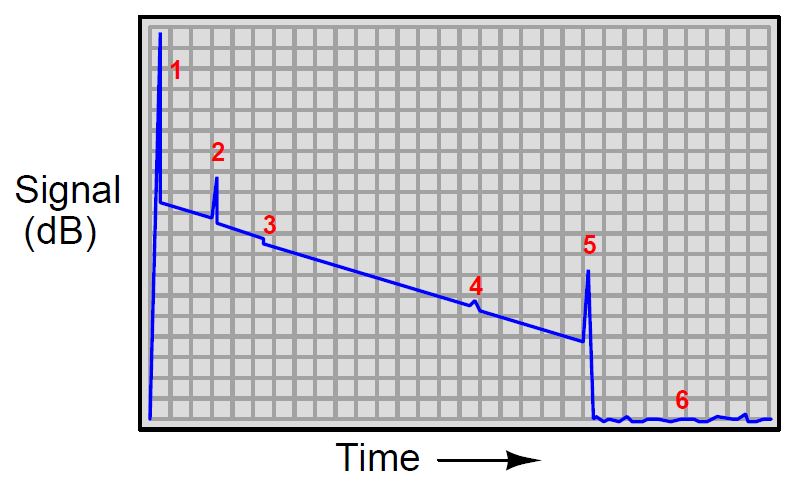
OTDR Graph

Legend:

  1. Incident pulse output by the OTDR, and injected into the launch fiber
  2. Reflection off the face of the near-end connection between the launch fiber and the fiber under test
  3. Loss of light due to a non-reflective discontinuity (e.g. sharp bend, splice)
  4. Loss of light due to a reflective discontinuity (e.g. mis-aligned connector)
  5. Reflection off the face of the far-end connection at the end of the fiber under test
  6. The “noise floor”

As you can see, an OTDR trace provides much more information about the performance of an optical fiber than a simple power test. Each flaw in the cable or its associated connectors appears as a deviation from the normal downward-sloped line of the trace, the location in time revealing the distance between the OTDR and the flaw. Thus, an OTDR not only indicates the nature of each flaw, and the amount of optical power lost at each flaw, but also the location of each flaw along the fiber’s length.

One important caveat exists for this distance calculation, and that is the fact that the length of a fiber in a multi-fiber cable will always be somewhat longer than the length of the cable itself, since individual fibers inside a cable are often “wound” in a spiral configuration or otherwise deviating from the straight centerline of the cable. “Loose tube” cables, for example, often exhibit fiber lengths 5% to 10% greater than the physical length of the cable itself.

Don't Miss Our Updates
Be the first to get exclusive content straight to your email.
We promise not to spam you. You can unsubscribe at any time.
Invalid email address
You've successfully subscribed !

Continue Reading

Fieldbus vs 4-20mA
What is IPSec? – Internet Protocol Security
HART Communication Problems
Industrial Automation Communication Protocols
Fieldbus Cables
What is HART- IP ?
Share This Article
Facebook Whatsapp Whatsapp LinkedIn Copy Link
Share
1 Comment
  • Munmun kumar says:
    August 3, 2023 at 2:18 pm

    What is different between jointing and splicing. Why we do splice OFC not jointing…

    Thanking you

    Reply

Leave a Reply Cancel reply

Your email address will not be published. Required fields are marked *

Stay Connected

128.3kFollowersLike
69.1kFollowersFollow
210kSubscribersSubscribe
38kFollowersFollow

Categories

Explore More

Purpose of Gateways, Bridges & Routers in Networking
H1 FF Data Link layer
What is a Network ?
DNP3 Communication Protocol Overview
Field Transmitter Communication Troubleshooting
What is Profibus? – A Comprehensive Guide for Beginners
Temperature Switch Principle
FF Function block Modes

Keep Learning

Control Valve Tubing

Instrument Tube Bending

DHCP

Difference Between BOOTP and DHCP

National Pipe Thread Cross Sectional View

What is Tapered Thread Pipe Fittings ?

Dissolved oxygen measurement using Optical Fiber Communication

Fiber Optic Sensors

Differential signals with RS485

RS485 Serial Communication

Input function blocks

FF Function Blocks

HART Communication Interview Questions

HART Communication Interview Questions and Answers

Modbus Communication Interview Questions and Answers

Modbus Communication Interview Questions and Answers

Learn More

Pressure gauge mechanism

How Measurement Span of Pressure Gauge Could be Changed?

What Happens When a Pump Runs Dry

What Happens When a Pump Runs Dry? How to Avoid it?

Orifice Flow Measurement Formula

Basics of Flow Measurement

SMART Transmitters Block Diagram

Smart Transmitters LRV & URV

Objective Questions of Building Fire and Gas Detectors

Objective Questions of Building Fire and Gas Detectors

Repeat Safety Valve Popping

Repeat Safety Valve Popping caused Urea Plant Shutdown

Digital Electronics Objective Questions

Digital Electronics Objective Questions – Set 9

Motor Rotating Magnetic Field

AC Motor Theory

Menu

  • About
  • Privacy Policy
  • Copyright

Quick Links

  • Learn PLC
  • Helping Hand
  • Part Time Job

YouTube Subscribe

Follow US
All rights reserved. Reproduction in whole or in part without written permission is prohibited.
Welcome Back!

Sign in to your account

Username or Email Address
Password

Lost your password?