Inst ToolsInst ToolsInst Tools
  • Courses
  • Automation
    • PLC
    • Control System
    • Safety System
    • Communication
    • Fire & Gas System
  • Instrumentation
    • Design
    • Pressure
    • Temperature
    • Flow
    • Level
    • Vibration
    • Analyzer
    • Control Valve
    • Switch
    • Calibration
    • Erection & Commissioning
  • Interview
    • Instrumentation
    • Electrical
    • Electronics
    • Practical
  • Q&A
    • Instrumentation
    • Control System
    • Electrical
    • Electronics
    • Analog Electronics
    • Digital Electronics
    • Power Electronics
    • Microprocessor
  • Request
Search
  • Books
  • Software
  • Projects
  • Process
  • Tools
  • Basics
  • Formula
  • Power Plant
  • Root Cause Analysis
  • Electrical Basics
  • Animation
  • Standards
  • 4-20 mA Course
  • Siemens PLC Course
Reading: Fiber Optic Cable Testing
Share
Font ResizerAa
Inst ToolsInst Tools
Font ResizerAa
  • Courses
  • Design
  • PLC
  • Interview
  • Control System
Search
  • Courses
  • Automation
    • PLC
    • Control System
    • Safety System
    • Communication
    • Fire & Gas System
  • Instrumentation
    • Design
    • Pressure
    • Temperature
    • Flow
    • Level
    • Vibration
    • Analyzer
    • Control Valve
    • Switch
    • Calibration
    • Erection & Commissioning
  • Interview
    • Instrumentation
    • Electrical
    • Electronics
    • Practical
  • Q&A
    • Instrumentation
    • Control System
    • Electrical
    • Electronics
    • Analog Electronics
    • Digital Electronics
    • Power Electronics
    • Microprocessor
  • Request
Follow US
All rights reserved. Reproduction in whole or in part without written permission is prohibited.
Inst Tools > Blog > Communication > Fiber Optic Cable Testing

Fiber Optic Cable Testing

Fiber optic cable testing is done to ensure all installed cable lengths and connectors are functioning properly.

Last updated: August 29, 2020 10:23 am
Editorial Staff
Communication eBooks
No Comments
Share
5 Min Read
SHARE

Optical fibers, like electrical communications cable, may need to be tested to measure certain performance characteristics. Such testing is commonplace for new installations of fiber optic cabling to ensure all installed cable lengths and connectors are functioning properly. Repeated tests over time, compared with the initial installation test, quantifies any degradation of cables or connectors.

Another common testing procedure, called acceptance testing, tests the optical cable while it is still on the spool prior to installation.

Two basic types of optical fiber tests are presented here: one where the power level of light is measured at the far end of the fiber from a source of known optical power, and another where a pulse of light is sent down a fiber and the light received at the same end of the fiber is analyzed.

The former test is simply a measurement of optical power, while the latter test is a sophisticated analysis of light over very brief periods of time (time domain reflectometry).

Optical power loss Testing

Perhaps the simplest quantitative test of an optical fiber consists of shining a light source of known optical power at one end of a fiber and monitoring the amount of optical power received at the other end of the fiber. This type of test is typically performed with two pieces of equipment: the source and the power meter.

First, the optical power meter and light source are short-coupled together using a pair of patch cables and a single “butt” connector:

Optical power loss testing

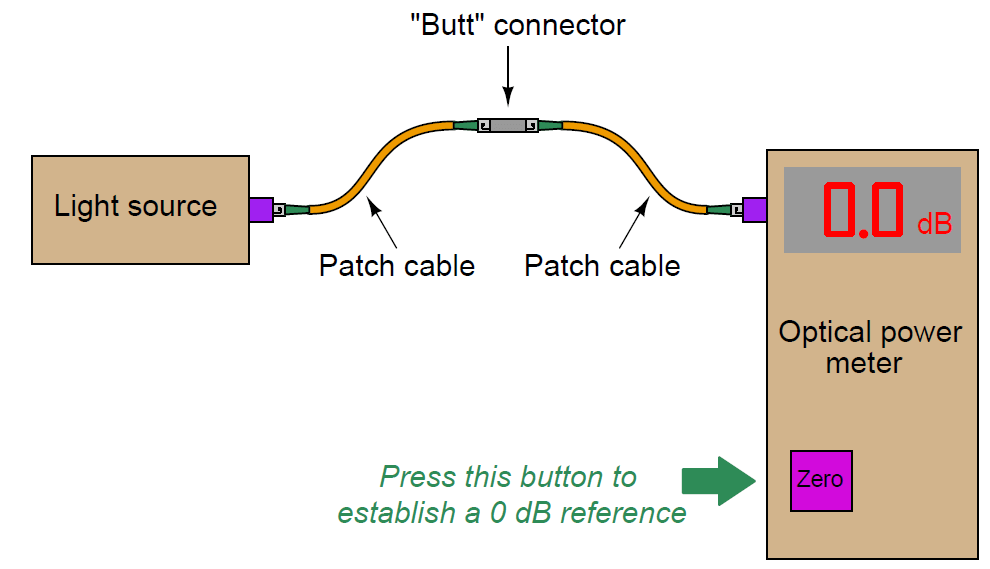
Once light is received by the optical power meter, the technician presses the “zero” button to set the baseline or reference point for all future power measurements. Although some light will be lost in the two patch cables and connector, this amount of loss will also be present in the final test and so it must be ignored.

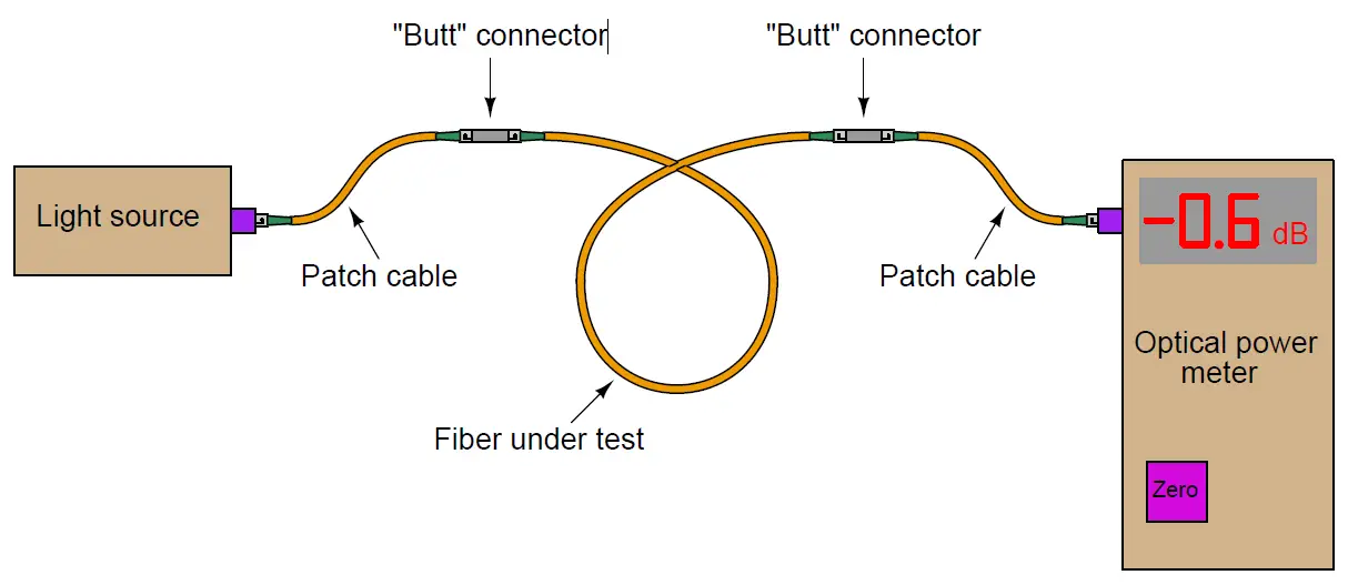
After “zeroing” the optical power meter, the actual fiber to be tested is connected between the light source and the power meter. Any additional light lost within the tested fiber will register at the power meter as a negative decibel figure:

Optical Cable power loss testing

Recall that the definition of a “decibel” is 10 times the common logarithm of the power ratio between output and input for any system:

Optical Cable loss Formula

Thus, the power loss of −0.6 dB shown in the illustration represents 87.1% of the optical source power received by the optical power meter. Decibels are very commonly used as an expression of power gain and loss in communication system testing, because dB figures directly add when components are connected in series with each other. For example, if we knew that a certain type of “butt” connector for optical fiber exhibited a typical power loss of −1.2 dB and that three of these connectors would be used to join a single run of fiber, we would know to expect a total connector loss of −3.6 dB (i.e. 3 × −1.2 dB).

Excessive optical power losses may be caused by a number of different factors, including:

  • Poor alignment between fibers in a connector → Connector flaw causing fibers to be mis-aligned (e.g. angular misalignment) → Fiber flaw causing mis-alignment in a good connector (e.g. cores not concentric)
  • Mismatched fiber sizes (e.g. 62.5 micron core sending light into a 50 micron core)
  • Oil or debris on the end of a connector
  • Rough (improperly polished) end on one or more fibers
  • Minimum bend radius violated at any point along the fiber’s length
  • Cracked fiber core

Unfortunately, a power meter test will not indicate what kind of flaw is causing excessive power loss, nor where that flaw might be located. If the cable in question has removable connectors midway in its length, the power meter and/or source may be relocated to test portions of the cable to determine which section contributes more to the power loss, but an end-to-end power test cannot pinpoint the location or the type of fault.

Also Read: OTDR Testing for Fiber Optic Cable

Don't Miss Our Updates
Be the first to get exclusive content straight to your email.
We promise not to spam you. You can unsubscribe at any time.
Invalid email address
You've successfully subscribed !

Continue Reading

Difference Between RS232 and RS485
Basics of AC Induction Motors
Foundation Fieldbus Device addressing
Ethernet Communication Interview Questions & Answers
What is Tapered Thread Pipe Fittings ?
Layer-2 and Layer-3 Network Switches
Share This Article
Facebook Whatsapp Whatsapp LinkedIn Copy Link
Share
Leave a Comment

Leave a Reply Cancel reply

Your email address will not be published. Required fields are marked *

Stay Connected

128.3kFollowersLike
69.1kFollowersFollow
210kSubscribersSubscribe
38kFollowersFollow

Categories

Explore More

Difference between Router, Switch, and Hub
Electrical Signal and Control Wiring
Surge Protection for the Fieldbus System
What is Profibus? – A Comprehensive Guide for Beginners
What is a Router? How Does a Router Work?
Network Switch Requirement in SCADA and DCS Architecture
H1 FF Physical layer
Fieldbus Analog Input Function Block

Keep Learning

Fieldbus Terminator

What is a Fieldbus Terminator and How Does it Work?

HART Protocol and Fieldbus Interview Questions

HART Protocol and Fieldbus Interview Questions

Pressure Switch Construction

Basics of Pressure switches

Important Networking Interview Questions

Important Networking Interview Questions

WirelessHART Network Protocol

WirelessHART Network Protocol

Control Valve Tubing

Instrument Tube Bending

HART Multidrop Network

What is HART Protocol ?

Difference Between Ethernet IP and EtherCAT

Difference Between Ethernet IP and EtherCAT

Learn More

Dual-junction thermocouple circuit

Find Thermocouple Ouput Voltage

Allen-Bradley MicroLogix PLC Wiring

Programmable Logic Controller (PLC) Questions and Answers – 8

What is Hydraulics

What is Hydraulics?

Digital Electronics Multiple Choice Questions

MOS Digital Integrated Circuits Objective Questions

Solenoid Valves Questions

Solenoid Valves Questions & Answers – 3

Earth Meter Working Principle

How Earth Resistance is Measured

PLC Ladder Logic Door Open and Closing System

Which Language is Best for PLC Programming?

Fieldbus coupling devices

Fieldbus Coupling Devices

Menu

  • About
  • Privacy Policy
  • Copyright

Quick Links

  • Learn PLC
  • Helping Hand
  • Part Time Job

YouTube Subscribe

Follow US
All rights reserved. Reproduction in whole or in part without written permission is prohibited.
Welcome Back!

Sign in to your account

Username or Email Address
Password

Lost your password?