Inst ToolsInst ToolsInst Tools
  • Courses
  • Videos
  • Q & A
    • Interview
      • Instrumentation
      • Electronics
      • Electrical
      • Practical Questions
    • MCQ
      • Instrumentation MCQ
      • Electrical MCQ
      • Electronics MCQ
      • Control Systems MCQ
      • Analog Electronics MCQ
      • Digital Electronics MCQ
      • Power Electronics MCQ
      • Microprocessor MCQ
      • Multiple Choice Questions
  • EE
    • Electronics
      • Electronics Q & A
      • Electronic Basics
      • Electronic Devices & Circuits
      • Electronics Animation
      • Digital Electronics
    • Electrical
      • Electrical Basics
      • Electrical Q & A
      • Power Electronics
      • Electrical Machines
      • Electrical Animation
      • Power Systems
      • Switchgear & Protection
      • Transmission & Distribution
  • Measure
    • Control Valves
    • Calibration
    • Temperature
    • Pressure
    • Flow
    • Level
    • Analyzers
    • Switches
    • Vibration
    • Solenoid Valve
  • Control
    • PLC Tutorials
    • Control Systems
    • Safety Instrumented System (SIS)
    • Communication
    • Fire & Gas System
  • More
    • Design
    • Tools
    • Animation
    • Basics
    • Formulas
    • Standards
    • TextBooks
    • Common
    • Software
    • Excel Tools
    • Erection & Commissioning
    • Process Fundamentals
    • Videos
    • Books
Search
All rights reserved. Reproduction in whole or in part without written permission is prohibited.
Reading: Half Wave Voltage Doubler using Diodes
Share
Notification Show More
Font ResizerAa
Inst ToolsInst Tools
Font ResizerAa
  • Courses
  • PLC Tutorials
  • Control Systems
Search
  • Courses
  • Videos
  • Q & A
    • Interview
    • MCQ
  • EE
    • Electronics
    • Electrical
  • Measure
    • Control Valves
    • Calibration
    • Temperature
    • Pressure
    • Flow
    • Level
    • Analyzers
    • Switches
    • Vibration
    • Solenoid Valve
  • Control
    • PLC Tutorials
    • Control Systems
    • Safety Instrumented System (SIS)
    • Communication
    • Fire & Gas System
  • More
    • Design
    • Tools
    • Animation
    • Basics
    • Formulas
    • Standards
    • TextBooks
    • Common
    • Software
    • Excel Tools
    • Erection & Commissioning
    • Process Fundamentals
    • Videos
    • Books
Follow US
All rights reserved. Reproduction in whole or in part without written permission is prohibited.
Inst Tools > Blog > Electronic Devices & Circuits > Half Wave Voltage Doubler using Diodes

Half Wave Voltage Doubler using Diodes

Last updated: October 5, 2016 12:46 pm
Editorial Staff
Electronic Devices & Circuits
No Comments
Share
2 Min Read
SHARE

Voltage multipliers use clamping action to increase peak rectified voltages without the necessity of increasing the transformer’s voltage rating. Multiplication factors of two, three, and four are common. Voltage multipliers are used in high-voltage, low-current applications such as cathode-ray tubes (CRTs) and particle accelerators.

Voltage Doubler

Half Wave Voltage Doubler

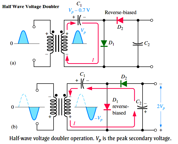
A voltage doubler is a voltage multiplier with a multiplication factor of two. A half-wave voltage doubler is shown in Below Figure. During the positive half-cycle of the secondary voltage, diode D1 is forward-biased and D2 is reverse-biased. Capacitor C1 is charged to the peak of the secondary voltage (Vp) less the diode drop with the polarity shown in part (a). During the negative half-cycle, diode D2 is forward-biased and D1 is reverse-biased, as shown in part (b). Since C1 can’t discharge, the peak voltage on C1 adds to the secondary voltage to charge C2 to approximately 2Vp. Applying Kirchhoff’s law around the loop as shown in part (b), the voltage across C2 is

VC1 – VC2 + Vp = 0

VC2 = Vp + VC1

Neglecting the diode drop of D2, VC1 = Vp. Therefore,

VC2 = Vp + Vp = 2Vp

half-wave-voltage-doubler-using-diodes

Under a no-load condition, C2 remains charged to approximately 2Vp. If a load resistance is connected across the output, C2 discharges slightly through the load on the next positive half-cycle and is again recharged to 2Vp on the following negative half-cycle. The resulting output is a half-wave, capacitor-filtered voltage. The peak inverse voltage across each diode is 2Vp. If the diode were reversed, the output voltage across C2 would have the opposite polarity.
Don't Miss Our Updates
Be the first to get exclusive content straight to your email.
We promise not to spam you. You can unsubscribe at any time.
Invalid email address
You've successfully subscribed !

Recommended Articles

What is Kirchhoff’s Current Law
Time Base Generator
Peak Inverse Voltage of Center Tap Rectifier
Bridge Rectifier Working Animation
Basics of Voltage Regulators
Full Wave Rectifier
Share This Article
Facebook Whatsapp Whatsapp LinkedIn Copy Link
Share
Leave a Comment

Leave a Reply Cancel reply

Your email address will not be published. Required fields are marked *

Stay Connected

128.3kFollowersLike
69.1kFollowersFollow
208kSubscribersSubscribe
38kFollowersFollow

Categories

Recent Comments

  • William Snyder on Top Non-PLC Certification Courses for Automation Professionals
  • Kamli on Top Free PLC Software
  • Guifty Shimica on Top Non-PLC Certification Courses for Automation Professionals
  • Guifty Shimica on Top Non-PLC Certification Courses for Automation Professionals

Related Articles

How a Multi Color LED Works

How a Multi Color LED Works ?

Transistor as an Amplifier in Common Emitter

Transistor as an Amplifier in Common Emitter

transistor-biasing-circuits

Summary Of Transistor Bias Circuits

kirchhoffs-voltage-law

What is Kirchhoff’s Voltage Law

Classification of Bridge Circuits

Classification of Bridge Circuits

phototransistor symbols

Phototransistor Working Principle

Transistor Load Line Analysis

Transistor Load Line Analysis

diode-limiter-principle

Diode Limiters/Clippers Operation

More Articles

Ziegler-Nichols closed-loop Formula

Tuning a Temperature Process Control Loop

Difference Between Modbus and Profibus

Difference Between Modbus and Profibus

how-to-select-a-fuse

How to Select a Fuse ?

Types of Failures in Control Valves

Types of Failures in Control Valves

Streams After Electrical Engineering Graduation

Streams After Electrical Engineering Graduation

Automatic Coffee Machine

Automatic Coffee Vending Machine – PLC Logic Programming

Advantages and Disadvantages of Network Topology

Advantages and Disadvantages of Air Blast Circuit Breakers

Transistor Stabilisation

Transistor Stabilisation

Follow US
All rights reserved. Reproduction in whole or in part without written permission is prohibited.
Welcome Back!

Sign in to your account

Username or Email Address
Password

Lost your password?