Inst ToolsInst ToolsInst Tools
  • Ask
  • Courses
  • Videos
  • Q & A
    • Interview
      • Instrumentation
      • Electronics
      • Electrical
      • Practical Questions
    • MCQ
      • Instrumentation MCQ
      • Electrical MCQ
      • Electronics MCQ
      • Control Systems MCQ
      • Analog Electronics MCQ
      • Digital Electronics MCQ
      • Power Electronics MCQ
      • Microprocessor MCQ
      • Multiple Choice Questions
  • EE
    • Electronics
      • Electronics Q & A
      • Electronic Basics
      • Electronic Devices & Circuits
      • Electronics Animation
      • Digital Electronics
    • Electrical
      • Electrical Basics
      • Electrical Q & A
      • Power Electronics
      • Electrical Machines
      • Electrical Animation
      • Power Systems
      • Switchgear & Protection
      • Transmission & Distribution
  • Measure
    • Control Valves
    • Calibration
    • Temperature
    • Pressure
    • Flow
    • Level
    • Analyzers
    • Switches
    • Vibration
    • Solenoid Valve
  • Control
    • PLC Tutorials
    • Control Systems
    • Safety Instrumented System (SIS)
    • Communication
    • Fire & Gas System
  • More
    • Design
    • Tools
    • Animation
    • Basics
    • Formulas
    • Standards
    • TextBooks
    • Common
    • Software
    • Excel Tools
    • Erection & Commissioning
    • Process Fundamentals
    • Videos
    • Books
Search
All rights reserved. Reproduction in whole or in part without written permission is prohibited.
Reading: Ideal Diode Characteristics
Share
Notification Show More
Font ResizerAa
Inst ToolsInst Tools
Font ResizerAa
  • Courses
  • PLC Tutorials
  • Control Systems
Search
  • Ask
  • Courses
  • Videos
  • Q & A
    • Interview
    • MCQ
  • EE
    • Electronics
    • Electrical
  • Measure
    • Control Valves
    • Calibration
    • Temperature
    • Pressure
    • Flow
    • Level
    • Analyzers
    • Switches
    • Vibration
    • Solenoid Valve
  • Control
    • PLC Tutorials
    • Control Systems
    • Safety Instrumented System (SIS)
    • Communication
    • Fire & Gas System
  • More
    • Design
    • Tools
    • Animation
    • Basics
    • Formulas
    • Standards
    • TextBooks
    • Common
    • Software
    • Excel Tools
    • Erection & Commissioning
    • Process Fundamentals
    • Videos
    • Books
Follow US
All rights reserved. Reproduction in whole or in part without written permission is prohibited.
Inst Tools > Blog > Electronic Devices & Circuits > Ideal Diode Characteristics

Ideal Diode Characteristics

Last updated: October 4, 2016 9:26 am
Editorial Staff
Electronic Devices & Circuits
No Comments
Share
2 Min Read
SHARE

The ideal model of a diode is the least accurate approximation and can be represented by a simple switch. When the diode is forward-biased, it ideally acts like a closed (on) switch, as shown in Figure (a). When the diode is reverse-biased, it ideally acts like an open (off) switch, as shown in part (b). Although the barrier potential, the forward dynamic resistance, and the reverse current are all neglected, this model is adequate for most troubleshooting when you are trying to determine if the diode is working properly.

Ideal Diode Characteristics


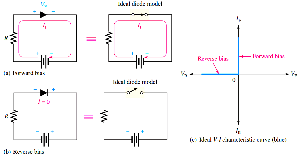
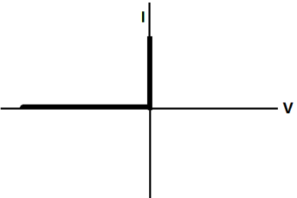
In Figure c), the ideal V-I characteristic curve graphically depicts the ideal diode operation. Since the barrier potential and the forward dynamic resistance are neglected, the diode is assumed to have a zero voltage across it when forward-biased, as indicated by the portion of the curve on the positive vertical axis.

VF = 0 V

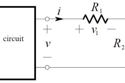
The forward current is determined by the bias voltage and the limiting resistor using Ohm’s law.

ideal-diode-current


Since the reverse current is neglected, its value is assumed to be zero, as indicated in Figure (c) by the portion of the curve on the negative horizontal axis.

IR = 0 A

The reverse voltage equals the bias voltage.

VR = VBIAS

You may want to use the ideal model when you are troubleshooting or trying to figure out the operation of a circuit and are not concerned with more exact values of voltage or current.

Don't Miss Our Updates
Be the first to get exclusive content straight to your email.
We promise not to spam you. You can unsubscribe at any time.
Invalid email address
You've successfully subscribed !
Phototransistor Working Principle
Characteristics of Photo diode
Dependent Current Source
Seven Segment Display Working Principle
Comparison of MOSFET and BJT
Share This Article
Facebook Whatsapp Whatsapp LinkedIn Copy Link
Share
Leave a Comment

Leave a Reply Cancel reply

Your email address will not be published. Required fields are marked *

Stay Connected

128.3kFollowersLike
69.1kFollowersFollow
208kSubscribersSubscribe
38kFollowersFollow

Categories

Recent Comments

  • Guifty Shimica on Top Non-PLC Certification Courses for Automation Professionals
  • Guifty Shimica on Top Non-PLC Certification Courses for Automation Professionals
  • MIHARITSOA Aina Sitraka on Top Non-PLC Certification Courses for Automation Professionals
  • Vaishnavi on Free Instrumentation Course for Trainee Engineers

Related Articles

pn-junction-energy-diagrams

Energy Diagrams of PN Junction & Depletion Region

Applications of Photo diodes

Applications of Photo diodes

Open Circuit without Freewheeling diode

Freewheeling Diode Working Principle

Cathode Ray Tube Deflection System

Cathode Ray Tube Deflection System

pn-junction-with-depletion-layer

How a PN Junction Formed in a Diode

capacitor-filter

Capacitor Filter Working Principle

Transistor as an Amplifier in Common Emitter

Transistor as an Amplifier in Common Emitter

PIN Diode Working Principle

PIN Diode Working Principle

More Articles

Switched Mode Power Supply (SMPS)

How does SMPS Works? – Switched Mode Power Supply

RTD Connection Diagram

Difference Between 2 wire RTD, 3 wire RTD, and 4 wire RTD’s

Float Level Switch Principle

Float Level Switch Working Principle Animation

temperature_calculator

Thermocouple / RTD Calculator

Absolute Pressure Gauges Principle

Absolute Pressure Gauges Principle

Pneumatic Relay

Pneumatic Relay Questions

Digital Electronics Multiple Choice Questions

Memory Devices Objective Questions – Part 5

gate-valve-principle-animation

Basics of Gate Valves

Follow US
All rights reserved. Reproduction in whole or in part without written permission is prohibited.
Welcome Back!

Sign in to your account

Username or Email Address
Password

Lost your password?