Inst ToolsInst ToolsInst Tools
  • Ask
  • Courses
  • Videos
  • Q & A
    • Interview
      • Instrumentation
      • Electronics
      • Electrical
      • Practical Questions
    • MCQ
      • Instrumentation MCQ
      • Electrical MCQ
      • Electronics MCQ
      • Control Systems MCQ
      • Analog Electronics MCQ
      • Digital Electronics MCQ
      • Power Electronics MCQ
      • Microprocessor MCQ
      • Multiple Choice Questions
  • EE
    • Electronics
      • Electronics Q & A
      • Electronic Basics
      • Electronic Devices & Circuits
      • Electronics Animation
      • Digital Electronics
    • Electrical
      • Electrical Basics
      • Electrical Q & A
      • Power Electronics
      • Electrical Machines
      • Electrical Animation
      • Power Systems
      • Switchgear & Protection
      • Transmission & Distribution
  • Measure
    • Control Valves
    • Calibration
    • Temperature
    • Pressure
    • Flow
    • Level
    • Analyzers
    • Switches
    • Vibration
    • Solenoid Valve
  • Control
    • PLC Tutorials
    • Control Systems
    • Safety Instrumented System (SIS)
    • Communication
    • Fire & Gas System
  • More
    • Design
    • Tools
    • Animation
    • Basics
    • Formulas
    • Standards
    • TextBooks
    • Common
    • Software
    • Excel Tools
    • Erection & Commissioning
    • Process Fundamentals
    • Videos
    • Books
Search
All rights reserved. Reproduction in whole or in part without written permission is prohibited.
Reading: 4-Wire, Three-Phase Delta Wiring System
Share
Notification Show More
Font ResizerAa
Inst ToolsInst Tools
Font ResizerAa
  • Courses
  • PLC Tutorials
  • Control Systems
Search
  • Ask
  • Courses
  • Videos
  • Q & A
    • Interview
    • MCQ
  • EE
    • Electronics
    • Electrical
  • Measure
    • Control Valves
    • Calibration
    • Temperature
    • Pressure
    • Flow
    • Level
    • Analyzers
    • Switches
    • Vibration
    • Solenoid Valve
  • Control
    • PLC Tutorials
    • Control Systems
    • Safety Instrumented System (SIS)
    • Communication
    • Fire & Gas System
  • More
    • Design
    • Tools
    • Animation
    • Basics
    • Formulas
    • Standards
    • TextBooks
    • Common
    • Software
    • Excel Tools
    • Erection & Commissioning
    • Process Fundamentals
    • Videos
    • Books
Follow US
All rights reserved. Reproduction in whole or in part without written permission is prohibited.
Inst Tools > Blog > Electrical Theory > 4-Wire, Three-Phase Delta Wiring System

4-Wire, Three-Phase Delta Wiring System

Last updated: October 3, 2018 11:12 am
Editorial Staff
Electrical Theory
No Comments
Share
2 Min Read
SHARE

Unlike the single-phase wiring scheme that must make a provision for a neutral leg and separate ground, the three-phase system needs neither a separate neutral nor a ground to operate safely. However, to prevent any unsafe condition, all 3- and 4-wire, three-phase systems can include an effective ground path. As with the previous single-phase discussion, only the secondary side of the transformer and its connected load need to be studied.

4-Wire, Three-Phase Delta Wiring System

The 4-wire, three-phase Delta system combines the ungrounded Delta previously above for three-phase loads with the convenience of the Edison system for single-phase loads. As depicted in the example illustration in below Figure, one side of the Delta has a grounded-neutral conductor connected to a center tap winding on one phase.

4-Wire, Three-Phase Delta Wiring System

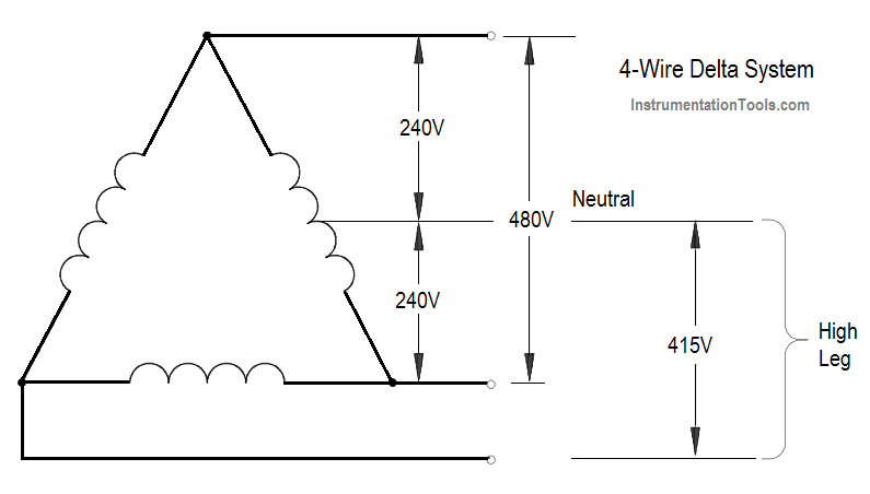
The single-phase voltage on each side of the half-tap is one-half the voltage available in the normal phase-to-phase relationship. This provides the same half- or full-voltage arrangement seen in the normal Edison scheme with a grounded neutral.

Notice also that the legs coming from the corners of the Delta would have a normal ungrounded appearance if it were not for the center tap of one phase. Thus, at any given location in the system, either three-phase power at full voltage or single-phase power with half or full voltage is equally possible.

However, there are several strict precautions that must be observed in the operation of this system. First, all loads must be carefully balanced on both the single-phase and three-phase legs. Second, because the voltage between one leg and the grounded neutral is considerably higher than the rest of the single-phase system, a measurement between the neutral and the phase must be taken to identify the “high leg,” or “bastard voltage.” Last, the “high leg” is never used as a single-phase source because no ground or grounded neutral exists for this circuit.

Don't Miss Our Updates
Be the first to get exclusive content straight to your email.
We promise not to spam you. You can unsubscribe at any time.
Invalid email address
You've successfully subscribed !
Series Resistance
Low Voltage Protection (LVP) and Low Voltage Release (LVR)
Induction Motor
D’Arsonval Meter Movement
DC Generator
Share This Article
Facebook Whatsapp Whatsapp LinkedIn Copy Link
Share
Leave a Comment

Leave a Reply Cancel reply

Your email address will not be published. Required fields are marked *

Stay Connected

128.3kFollowersLike
69.1kFollowersFollow
208kSubscribersSubscribe
38kFollowersFollow

Categories

Recent Comments

  • Kamli on Top Free PLC Software
  • Guifty Shimica on Top Non-PLC Certification Courses for Automation Professionals
  • Guifty Shimica on Top Non-PLC Certification Courses for Automation Professionals
  • MIHARITSOA Aina Sitraka on Top Non-PLC Certification Courses for Automation Professionals

Related Articles

Resistor Y and Delta Network Calculation

Y and Delta Resistor Network Calculations

Core-Type Transformer

Transformer Theory of Operation

Single Line Diagram

Single Line Diagram

Three-Phase Wye Wiring System

4-Wire, Three-Phase Wye Wiring System

Block Diagram

Block Diagram

Electrical Symbols

Electrical Symbols

Motor Rotating Magnetic Field

AC Motor Theory

Moving Iron Vane Meter Movement

Moving Iron Vane Meter Movement

More Articles

PLC Automatic Pedal Switch for Speed Control

PLC Automatic Pedal Switch for Speed Control

Top 100 555 Timer Projects for Engineering Students

Top 555 Timer Projects for Engineering Students

Electron Gun of CRT

Electron Gun of Cathode Ray Tube

Temperature Measurement Questions

Interview Questions on Temperature Measurement

grounded thermocouple junction

Types of Thermocouple Measuring Junction

Argonite/CO2 Flooding System Master & Slave Cylinder Operation

Spot Type Fixed Temperature Heat Detector Principle

Fixed Temperature Heat Detector Working Principle

Pressure Gauge Maintenance and Troubleshooting

Pressure Gauge Maintenance and Troubleshooting

Follow US
All rights reserved. Reproduction in whole or in part without written permission is prohibited.
Welcome Back!

Sign in to your account

Username or Email Address
Password

Lost your password?