4-20 mA Loop Splitter
Problems with Current Loop Loads in Series

Not so good: A single 4-20 mA loop from a sensor is connector to a panel meter, a external control valve, a recorder, a local controller, a local switch, a third party data logger and a PLC in series. If the loop opens, all devices in the loop fail.
- All devices in the loop cannot share a common ground, but must be electrically floating. This is often not possible.
- When any device in a loop is removed, fails, or if a wiring fault occurs, all other devices in the loop loose their 4-20 mA signal.
- The transmitter(signal conditioner) voltage compliance limit may be exceeded, since the voltage drops across loads in series are additive.
- The 4-20 mA signal to each load device cannot be individually adjusted for calibration purposes.
- There are not diagnostics for the current to each load.
Loop Splitter / Retransmitter Solution
Why a Loop Splitter is Needed ?
In many industrial systems, the same 4-20 mA signal from a transmitter is sent to multiple devices in series, such as panel meters, chart recorders and PLCs, as shown below. When any device in the loop is removed, fails, or suffers a wiring fault, all other devices will then also lose their 4-20 mA signal.
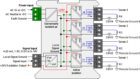
Much better: Four independent 4-20 mA loops with ±10V common mode isolation. If any of the output loops opens, only a single device is affected. The output loops can share a common ground.
- Sources up to four (4) independently adjustable 4-20 mA outputs from a single input, which can be 4-20 mA, 1-5V, 0-5V or 0-10V, as selected by jumpers. ( Note : Number of outputs depends on loop splitter model )
- If any device in an output loop is removed from a loop or fails, or if a wiring fault occurs in any loop, the other loops continue to operate properly.
- Signal input and outputs can share a common signal ground.
- Common mode volage of output loops is ±10V by means of active circuity so that remote grounds can vary by up to ±10V.
- Each loop only drives a single load, thus avoiding voltage compliance problems.
- ±10% of zero and span adjustment are provided for each output loop to allow for independent loop calibration.
- Diagnostics for each output loop are provided by a yellow LED lamp to indicate loop continuity and by a test point across a 10Ω series resistor, where 200 mV corresponds to 20 mA. The test point allows a multimeter to measure the loop current without breaking the loop.
- Power for the loop splitter can be 85-264 Vac or low voltage 10-48 Vdc or 12-32 Vac (Vary from model to model). An excitation output is provided on the signal input side to drive a 2- or 3-wire transmitter at 24 Vdc up to 30 mA.
Theory of Operation
The loop splitters convert a 4-20mA process current input into two/four identical isolated 4-20mA output signals. Power is obtained from the output loop (sinks current).
Each channel operates independently to prevent interaction between channels. Galvanic isolation eliminates ground loops, reduces noise, and blocks transient signals. Splitters are available in 2-wire loop-powered and 4-wire AC/DC-powered models.
The loop powered model runs on 12-50 VDC power from the output loop, has a built-in isolated excitation supply with short circuit protection, and can drive up to two/four field 2-wire process loops.
Galvanic & Active Isolation:
A single input current loop is split into four independent output loops I1, I2, I3 and I4 by four current generators. The input and output signals are galvanically isolated from power and earth grounds by up to 264 Vac.
Active circuitry allows a common mode voltage up to ±10V between Local Signal Ground (on pins 1) and the Remote Grounds.
Each common mode voltages, labeled CMV1 to CMV4 in the diagram, reflects the actual voltage difference between Local Signal Ground and the Remote Ground. Such differences can be caused by current flows in the factory.
Floating loads:
Any output load R that is floating (not connected to Earth Ground or a Local Ground) can be connected between current output (Pin 1) and current return (Pin 2). Current return is internally tied to Signal Ground, which can be floating or be connected to Earth Ground.
Grounded loads:
Any output load R can be connected to a Local Ground instead of current return. The Remote Grounds can each be different, but can only differ from Signal Ground by a safe common mode voltage CMV. Signal Ground should be tied to Earth Ground to minimize noise pickup.
Application
- Isolation and conversion of standard DC signals.
- Galvanic separation of analog current and voltage signals. Elimination of ground loops and measurement of floating signals.
- A competitive choice in terms of both price and technology for galvanic isolation of current and voltage signals to SCADA systems or PLC equipment.
- Installation in ATEX Ex zone 2 / IECEx zone 2 / FM division 2. Suitable for environments with high vibration stress
Source : laurels




U r awesome dear .pls keep it up. Really hardworking . best of wishes.
very good can u mail me the documents
I came across this few weeks ago. The notes really explain it well
Hi, may i have 1 signal of 4 to 20mA input to more than 4 isolated 4 to 20mA output? For example: 14 outputs.