Inst ToolsInst ToolsInst Tools
  • Courses
  • Automation
    • PLC
    • Control System
    • Safety System
    • Communication
    • Fire & Gas System
  • Instrumentation
    • Design
    • Pressure
    • Temperature
    • Flow
    • Level
    • Vibration
    • Analyzer
    • Control Valve
    • Switch
    • Calibration
    • Erection & Commissioning
  • Interview
    • Instrumentation
    • Electrical
    • Electronics
    • Practical
  • Q&A
    • Instrumentation
    • Control System
    • Electrical
    • Electronics
    • Analog Electronics
    • Digital Electronics
    • Power Electronics
    • Microprocessor
  • Request
Search
  • Books
  • Software
  • Projects
  • Process
  • Tools
  • Basics
  • Formula
  • Power Plant
  • Root Cause Analysis
  • Electrical Basics
  • Animation
  • Standards
  • 4-20 mA Course
  • Siemens PLC Course
Reading: What is a 3-way Solenoid Valve ?
Share
Notification Show More
Font ResizerAa
Inst ToolsInst Tools
Font ResizerAa
  • Courses
  • Design
  • PLC
  • Interview
  • Control System
Search
  • Courses
  • Automation
    • PLC
    • Control System
    • Safety System
    • Communication
    • Fire & Gas System
  • Instrumentation
    • Design
    • Pressure
    • Temperature
    • Flow
    • Level
    • Vibration
    • Analyzer
    • Control Valve
    • Switch
    • Calibration
    • Erection & Commissioning
  • Interview
    • Instrumentation
    • Electrical
    • Electronics
    • Practical
  • Q&A
    • Instrumentation
    • Control System
    • Electrical
    • Electronics
    • Analog Electronics
    • Digital Electronics
    • Power Electronics
    • Microprocessor
  • Request
Follow US
All rights reserved. Reproduction in whole or in part without written permission is prohibited.
Inst Tools > Blog > Control Valves > What is a 3-way Solenoid Valve ?

What is a 3-way Solenoid Valve ?

Last updated: April 13, 2019 2:28 pm
Editorial Staff
Control Valves Solenoid Valve
1 Comment
Share
4 Min Read
SHARE

3-way solenoid valves operate in a manner analogous to single-pole double-throw (SPDT) electrical switches: with two paths for flow sharing one common terminal.

Contents
3-way Solenoid Valve SchematicsCompare 2 way Solenoid and 3 way Solenoid Valves

3-way solenoid valves have three ports for fluid, and like 2-way valves may be referred to either as normally-open and normally-closed.

Ports on a pneumatic 3-way valve are commonly labeled with the letters “P,” “E,” and “C,” representing Pressure (compressed air supply), Exhaust (vent to atmosphere), and Cylinder (the actuating mechanism), respectively.

Alternatively, you may see the cylinder port labeled “A” (for actuator ) instead of “C”. If the solenoid valve is intended for use in a hydraulic (liquid) system, the letter “T” is customarily used to identify the return port rather than “E” (i.e. Tank rather than Exhaust):

3-way Solenoid Valve Schematics

3-way solenoid valve Normally Closed

3-way solenoid valve Normally Open

The letters used to label ports on a valve such as this not only denote those ports’ destinations, but also serve to mark which “box” of the valve’s symbol is the normal (resting) state.

In all fluid power diagrams you will see that only one of the boxes on each spool valve will have lines connecting to it and/or labels at the fluid ports, and that box is the one which will be aligned when the valve is not being actuated.

Alternatively, the numbers 1, 2, and 3 may be used to label the same ports. However, the numbers do not consistently refer to pressure source (P) and exhaust (E) ports, but rather to the 3-way valve’s “normal” versus “actuated” statuses.

A 3-way valve will pass fluid between ports 1 and 3 in its “normal” (resting) state, and pass fluid between ports 1 and 2 in its energized state.

The following table shows the correspondence between port numbers and port letters for both styles of 3-way solenoid valve:

3-way solenoid valve Details

Another way to think of this labeling is to consider port 1 the common, port 2 the normally-closed, and port 3 the normally-open, in a manner similar to SPDT (form-C) electrical switches.

Again, bear in mind that the words “open” and “closed” do not mean the same for fluid valves as they do for electrical switches.

A “normally-open” port on the valve permits fluid flow in its “normal” state, whereas a “normally-open” switch contact prevents electric current flow in its “normal” state.

As with 2-way solenoid valves, the arrows denote preferred direction of fluid flow. Bidirectional 3-way valves will be drawn with double-headed arrows (pointing both directions).

A different symbology is used in loop diagrams and P&IDs than that found in fluid power diagrams – one more resembling general instrumentation (ISA) valve symbols:

Compare 2 way Solenoid and 3 way Solenoid Valves

Compare 2 way Solenoid Valve and 3 Way Solenoid Valve

Regrettably, these symbols are not nearly as descriptive as those used in fluid power diagrams.

In order to show directions of flow (especially for 3-way valves), one must add arrows showing “normal” (resting, DE) flow directions:

3 Way Solenoid Valve NO and NC

Alternatively, a pair of arrows shows the directions of flow in both energized (E) and de-energized (D) states:

Three way solenoid valve Schematic

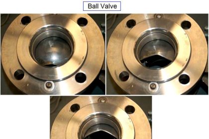
Photographs of an actual 3-way solenoid valve (this one manufactured by ASCO) appear here:

3-way solenoid valve images

A view of the nameplate for this particular solenoid valve reveals some of its ratings and characteristics:

Solenoid Valve nameplate details Specifications

Credits : by Tony R. Kuphaldt – under the terms and conditions of the Creative Commons Attribution 4.0 International Public License

Don't Miss Our Updates
Be the first to get exclusive content straight to your email.
We promise not to spam you. You can unsubscribe at any time.
Invalid email address
You've successfully subscribed !

Continue Reading

Calculate Flow Coefficient Kv of Solenoid Valve
Difference between Blowdown Valve (BDV) and Shutdown Valve (SDV) ?
Solenoid Valve Terminology Questions and Answers
Solenoid Valves Terminology
Directional Control Valves Working Principle
Solenoid Valve’s Energized or De-energized State ?
Share This Article
Facebook Whatsapp Whatsapp LinkedIn Copy Link
Share
1 Comment
  • Scottie Omar says:
    March 24, 2021 at 11:44 am

    It’s hard to say

    Reply

Leave a Reply Cancel reply

Your email address will not be published. Required fields are marked *

Stay Connected

128.3kFollowersLike
69.1kFollowersFollow
210kSubscribersSubscribe
38kFollowersFollow

Categories

Explore More

Basics of Actuators
Self Actuated Pressure Control Valve Functional Testing
Solving Control Valve Hunting: Instrument Troubleshooting
Safety Relief Valve Material Selection
Solenoid Valve Troubleshooting Practices
Digital Control Valves – Introduction, Principle, Setup, Applications
ESDV : How it Works ?
What is a 4-way Solenoid Valve?

Keep Learning

Tilting Disk Check Valve Principle

What is Tilting Disk Check Valve ?

Pilot operated Solenoid Valve Principle

How Pilot operated Solenoid Valve Works ?

Complementary Split Range Control

What is Complementary Split Range Control (CSRC)?

Emergency Block Valve

SIS Emergency Block Valves (EBV)

Valves Pressure Loss - Questions and Answers

Valves Pressure Loss – Questions and Answers

Snap Acting Relay Working Principle

Snap Acting Relay Working Principle

Online Testing of Solenoid Valve

Design and Accessories Required for Online Testing of Solenoid Valve

Solenoid Valve Functional Testing

Solenoid Valve Functional Testing

Learn More

Hydraulic Actuators

Working Principle of Hydraulic Actuators

Self-actuated Temperature Regulator

Self-actuated Temperature Regulator – Principle, Types, Advantages

Internet of Things (IOT)

History of Internet of Things (IOT)

Top Non-PLC Certification Courses for Automation Professionals

Top Non-PLC Certification Courses for Automation Professionals

Instrument Numbering Philosophy

Instrument Numbering Philosophy

Averaging Pitot Tube Principle

What is a Torbar? – Averaging Pitot Tubes

Allen-Bradley PLC

#15 PLC Best Practices – Safe State when PLC Restarts

Analysis Instrumentation Objective Questions

Analysis Instrumentation Objective Questions

Menu

  • About
  • Privacy Policy
  • Copyright

Quick Links

  • Learn PLC
  • Helping Hand
  • Part Time Job

YouTube Subscribe

Follow US
All rights reserved. Reproduction in whole or in part without written permission is prohibited.
Welcome Back!

Sign in to your account

Username or Email Address
Password

Lost your password?