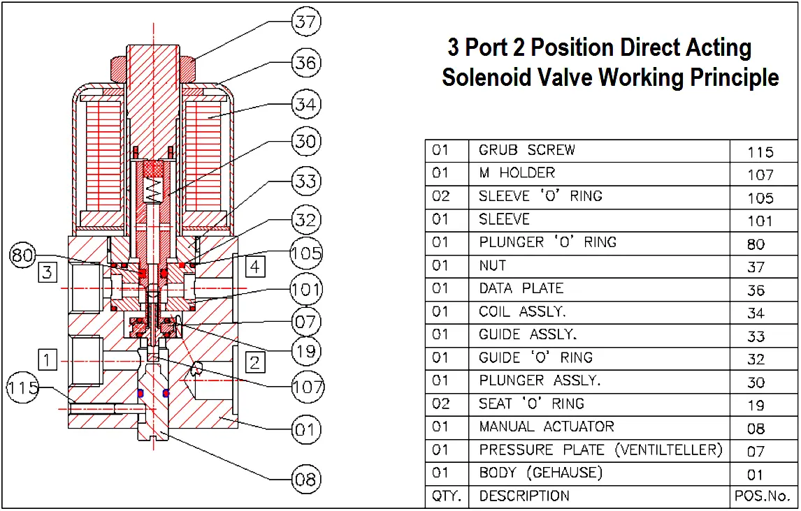
The valve is 3/2 Direct Acting pressure balance design i.e. area at the Seat (Part-19) and balancing Plunger O Ring (Part- 80) are same, thereby air force acting on the Plunger Seat is nullified which makes the valve to work merely on the spring force throughout its pressure range.
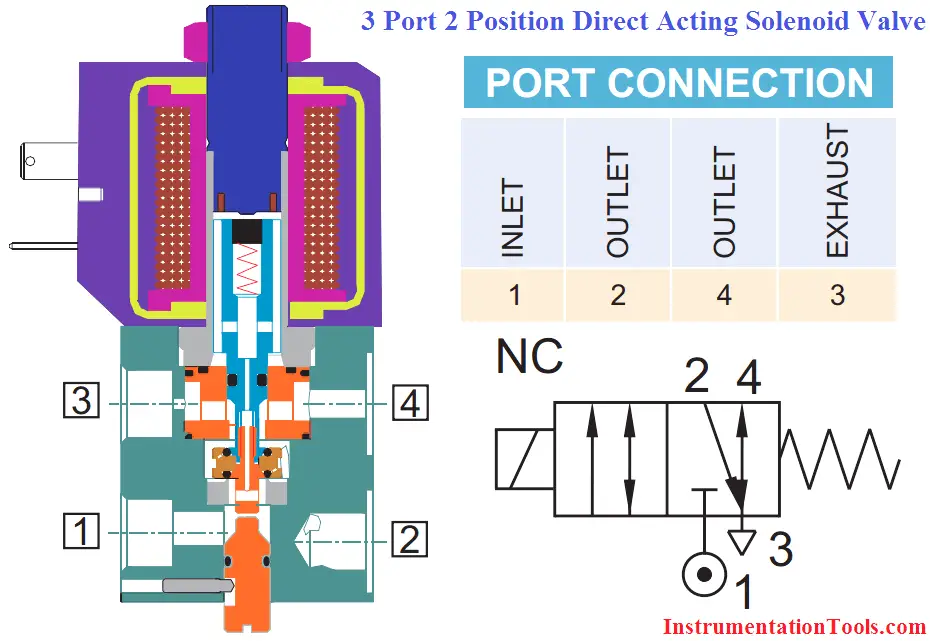
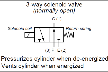
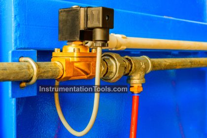
3 Port 2 Position Direct Acting Solenoid Valve
In the de-energised condition of the valve Port-1 is blocked and Port-3 is connection to Port-2. Port-4 is connected to spring chamber of the Actuator which is connected to Port-3 also.
On energizing the valve, Plunger (30) pulls up thereby connecting Port-1 and Port-2 and blocking Port-3. Port-4 remains connected to Exhaust Port-3. When the inlet is connected to Port-1, air passes through the small hole provided in the Plunger and acts on upper side of Plunger O Ring (80).
When the valve is energized, the Plunger (30) pulls up because of which the lower orifice opens up thereby connecting Port-1 to the outlet Port-3 and the upper orifice at Sleeve (Part-101) gets blocked.
In this condition force acting on the Plunger (30) due to seat at the Sleeve (Part-101) and on the Plunger (30) due to Plunger O Ring (80) are same because of their equal area.
When the valve is de-energised Port-2 gets connected to Port-3. However, as Port-3 has smaller opening as compared to its size, first air enters into the spring chambers through Port-4.
Manual Override Operation : Push & Turn Type
When the solenoid is de-energised and inlet and outlet ports connected to the applying rated pressure, the valve can be operated either pressing the Manual Override, when the same is released, the valve returns back to the normal position.
The valve can also be locked in energized position by pushing the Manual Override and rotating clockwise. To avoid Manual Override returning back to normal condition, ensure that the same is turned above 90º.
The valve can be brought to normal condition by turning Manual Override anti clockwise.
Testing of the Valve at the Test Bench
Check at least once in 3 years or following your routine maintenance schedule.
a) Apply rated pressure at inlet port of the valve.
b) Plug outlet port.
c) Check operation of the valve and leakage at the exhaust ports and pilot vent at the rated and minimum working pressure by applying 75% to 120% rated voltage.
d) While keeping the solenoid de-energised, check operation and leakage from exhaust and pilot vent ports of the valve at the rated and minimum working pressure by operating Manual Override.
e) Without connecting air supply to the valve, operate Manual Override. Energise and De-energise Solenoid to check for the plunger movement (normally movement should not be there) which can be checked by click sound. After operating Manual Override if plunger movement is found, reduce length of the manual override by 0.3mm from its taper end. Continue this till click sound stops.
f) Check the insulation resistance of the Solenoid by applying 500V DC at terminals and the solenoid housing. It should be more than 100 Mega Ohms.
Source: Rotex




Thanks for sharing knowledge.
How to differentiate between AC and Dc coil if nameplat is not present?
How much resistance should be there across healthy sol. coil terminals of AC and DC coil?
Thanks
Very good initiative taken by author Mr. REDDY. Thank you for the same on behalf of all learners. Very informative & Handy. I support this ” Let’s Learn” concept .