Inst ToolsInst ToolsInst Tools
  • Courses
  • Automation
    • PLC
    • Control System
    • Safety System
    • Communication
    • Fire & Gas System
  • Instrumentation
    • Design
    • Pressure
    • Temperature
    • Flow
    • Level
    • Vibration
    • Analyzer
    • Control Valve
    • Switch
    • Calibration
    • Erection & Commissioning
  • Interview
    • Instrumentation
    • Electrical
    • Electronics
    • Practical
  • Q&A
    • Instrumentation
    • Control System
    • Electrical
    • Electronics
    • Analog Electronics
    • Digital Electronics
    • Power Electronics
    • Microprocessor
  • Request
Search
  • Books
  • Software
  • Projects
  • Process
  • Tools
  • Basics
  • Formula
  • Power Plant
  • Root Cause Analysis
  • Electrical Basics
  • Animation
  • Standards
  • 4-20 mA Course
  • Siemens PLC Course
Reading: Zener Diode Limiter
Share
Notification Show More
Font ResizerAa
Inst ToolsInst Tools
Font ResizerAa
  • Courses
  • Design
  • PLC
  • Interview
  • Control System
Search
  • Courses
  • Automation
    • PLC
    • Control System
    • Safety System
    • Communication
    • Fire & Gas System
  • Instrumentation
    • Design
    • Pressure
    • Temperature
    • Flow
    • Level
    • Vibration
    • Analyzer
    • Control Valve
    • Switch
    • Calibration
    • Erection & Commissioning
  • Interview
    • Instrumentation
    • Electrical
    • Electronics
    • Practical
  • Q&A
    • Instrumentation
    • Control System
    • Electrical
    • Electronics
    • Analog Electronics
    • Digital Electronics
    • Power Electronics
    • Microprocessor
  • Request
Follow US
All rights reserved. Reproduction in whole or in part without written permission is prohibited.
Inst Tools > Blog > Electronic Devices & Circuits > Zener Diode Limiter

Zener Diode Limiter

Last updated: September 27, 2016 5:51 pm
Editorial Staff
Electronic Devices & Circuits
No Comments
Share
1 Min Read
SHARE

Zener diodes can be used in ac applications to limit voltage swings to desired levels. Below Figures shows three basic ways the limiting action of a zener diode can be used.

Zener Diode Limiter

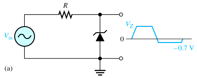
Part (a) shows a zener used to limit the positive peak of a signal voltage to the selected zener voltage. During the negative alternation, the zener acts as a forward-biased diode and limits the negative voltage to -0.7 V.

Zener Diode Limiter Working

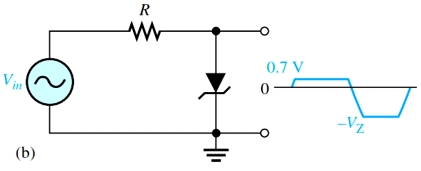
When the zener is turned around, as in part (b), the negative peak is limited by zener action and the positive voltage is limited to +0.7 V. Two back-to-back zeners limit both peaks to the zener voltage ;0.7 V, as shown in part (c).

Zener Diode Clipper

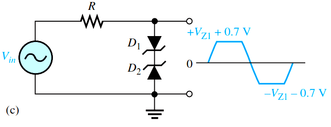
During the positive alternation, D2 is functioning as the zener limiter and D1 is functioning as a forward-biased diode. During the negative alternation, the roles are reversed.

Don't Miss Our Updates
Be the first to get exclusive content straight to your email.
We promise not to spam you. You can unsubscribe at any time.
Invalid email address
You've successfully subscribed !

Continue Reading

Cathode Ray Tube (CRT)
Combining Independent Current Sources in Parallel
Ripple Voltage in Rectifiers
Transistor as a Switch Working Principle
Optoisolator Working Principle
Transistor Amplifier Working Principle
Share This Article
Facebook Whatsapp Whatsapp LinkedIn Copy Link
Share
Leave a Comment

Leave a Reply Cancel reply

Your email address will not be published. Required fields are marked *

Stay Connected

128.3kFollowersLike
69.1kFollowersFollow
210kSubscribersSubscribe
38kFollowersFollow

Categories

Explore More

Phototransistor Circuit Example
Diodes Voltage Quadrupler
pi filter Operation
Transistor as Amplifier
Applications of Photo diodes
Full Wave Voltage Doubler using Diodes
What is Kirchhoff’s Voltage Law
Bipolar Junction Transistor Construction

Keep Learning

pn-junction-with-depletion-layer

How a PN Junction Formed in a Diode

Why Silicon is preferred over Germanium ?

Why Silicon is preferred over Germanium ?

transistor-base-bias

Transistor Base Bias

Insulators, Conductors and Semiconductors

Capacitor Filter Operation

Capacitor Filter Operation

Ideal Diode Characteristics Curve

Difference between ideal diode & conventional diode

Current Limiting Resistor

Resistors Principle & Applications

Basic DC Power Supply Circuit

Basic DC Power Supply Circuit

Learn More

Paddle Wheel Flow Meter

Paddle Wheel Flow Meters – Principle, Advantages, Limitations

Bolted to Vessel Flange Displacer Level Transmitter

Seal Level Differential Pressure Transmitter Problems

Proximity Switch PNP Type Working Animation

Proximity switches Circuit Diagram Operation

Industrial Instrumentation Quiz

Industrial Instrumentation Quiz

Digital Control Systems

Z & S Domain Relationship

port-guided globe valve plug

What is Port-guided Globe Valve ?

Current-to-Percentage-Conversion

Formula for Current 4-20ma to Percentage Conversion

Sensors and Transducers Objective Questions

Top 1000 Instrumentation Engineering Objective Questions

Menu

  • About
  • Privacy Policy
  • Copyright

Quick Links

  • Learn PLC
  • Helping Hand
  • Part Time Job

YouTube Subscribe

Follow US
All rights reserved. Reproduction in whole or in part without written permission is prohibited.
Welcome Back!

Sign in to your account

Username or Email Address
Password

Lost your password?