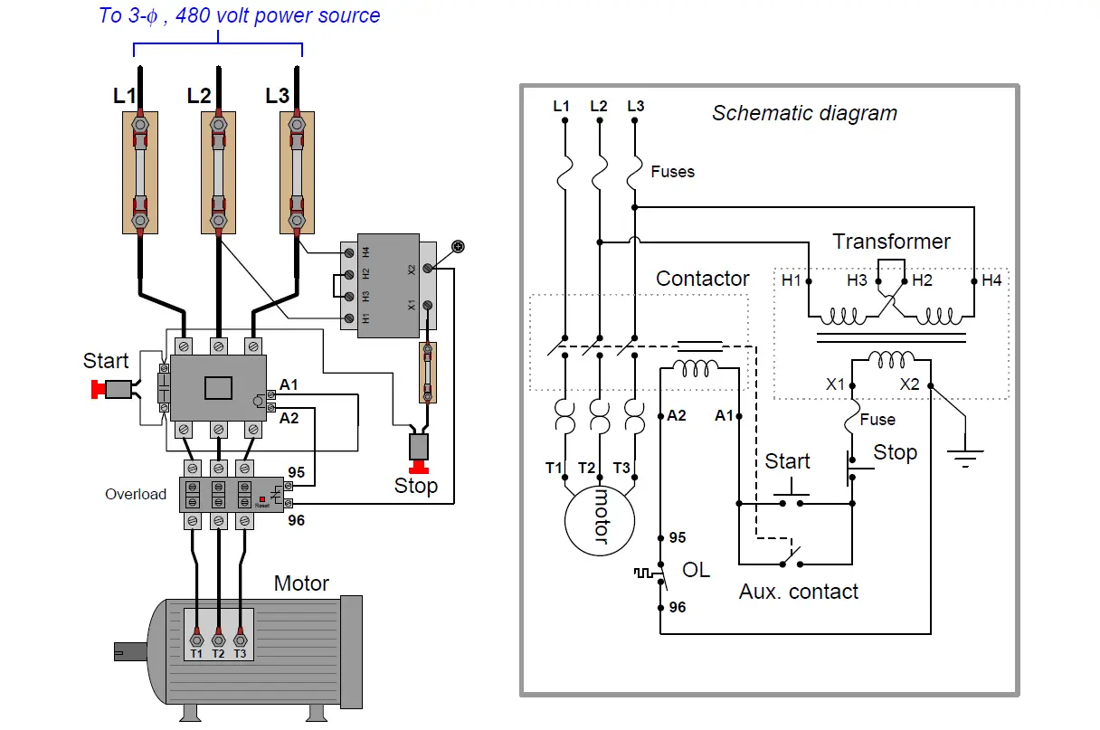
A simple three-phase, 480 volt AC motor-control circuit is shown here, both in pictorial and schematic form. This entire assembly consisting of contactor, overload block, control power transformer, power fuses (or alternatively, a circuit breaker) and associated components is informally referred to as a bucket :

Note how a control power transformer steps down the 480 volt AC to provide 120 volt AC power for the contactor coil to operate on. Furthermore, note how the overload (“OL”) contact is wired in series with the contactor coil so that a thermal overload event forces the contactor to de-energize and thus interrupt power to the motor even if the control switch is still in the “on” position. The overload heaters appear in the schematic diagram as pairs of back-to-back “hook” shapes, connected in series with the three “T” lines of the motor. Remember that these “OL” heater elements do not directly interrupt power to the motor in the event of an overload, but rather signal the “OL” contact to open up and de-energize the contactor.
Also Read : Motor Protection Circuits
In an automatic control system, the toggle switch would be replaced by another relay contact (that relay controlled by the status of a process), a process switch, or perhaps the discrete output channel of a programmable logic controller (PLC).
It should be noted that a toggling-style of switch is necessary in order for the motor to continue to run after a human operator actuates the switch. The motor runs when the switch is in the closed state, and stops when the switch opens. An alternative to this design is to build a latching circuit allowing the use of momentary contact switches (one to start, and one to stop).
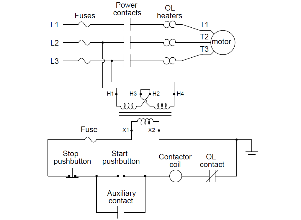
A simple latching motor control circuit is shown here:
In this circuit, an auxiliary contact actuated by the motor contactor is wired in parallel with the “Start” pushbutton switch, so that the motor contactor continues to receive power after the operator releases the switch. This parallel contact – sometimes called a seal-in contact – latches the motor in an “on” state after a momentary closure of the “Start” pushbutton switch.
A normally-closed “Stop” switch provides a means to “un-latch” the motor circuit. Pressing this pushbutton switch opens the control circuit, forcing current to halt through the coil of the contactor, which then opens the three motor power contacts as well as the auxiliary contact used to maintain the contactor’s energized state.
Also Read : Motor Starter Circuits
A simple ladder diagram showing the interconnections of all components in this motor control circuit makes this system easier to understand:
Most on/off motor control circuits in the United States are some variation on this wiring theme, if not identical to it. Once again, this system could be automated by replacing the “Start” and “Stop” pushbutton switches with process switches (e.g. pressure switches for an air compressor control system) to make a system that starts and stops automatically. A programmable logic controller (PLC) may also be used to provide the latching function rather than an auxiliary contact on the contactor. Once a PLC is included in the motor control circuit, a great many automatic control features may be added to enhance the system’s capabilities. Examples include timing functions, motor cycle count functions, and even remote start/stop capability via a digital network connecting to operator interface displays or other computers.
In applications where reversing motor control is desired, a pair of contactors may be wired together as shown here:
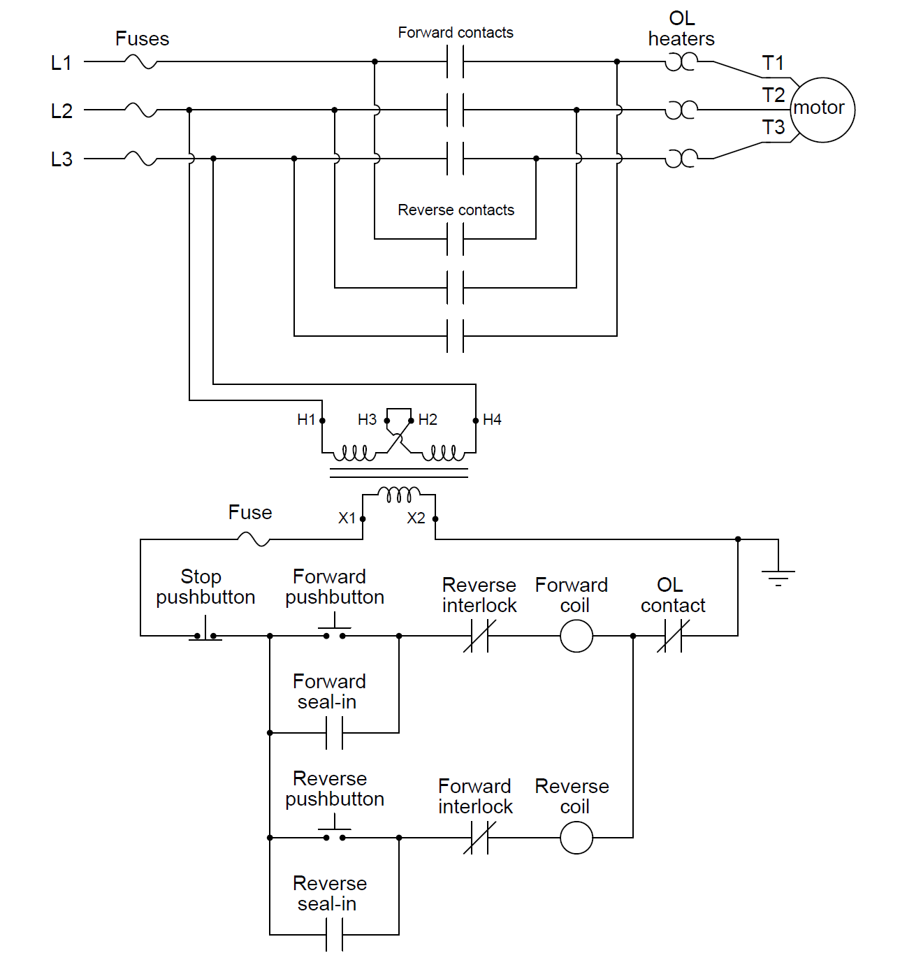
Note how motor reversal is accomplished by swapping phases L1 and L3: in the forward direction, power line conductor L1 connects to motor terminal T1, L2 connects to T2, and L3 connects to T3. In the reverse direction L2 still connects to T2, but L1 now connects to T3 and L3 now connects to T1. Recall the principle that swapping any two phases in a three-phase power system reverses the phase rotation, which in this case make the electric motor spin the other direction.
With two contactors, the control circuit now contains two coils to actuate those contactors: one marked “forward” and the other marked “reverse”. Separate “forward” and “reverse” pushbutton switches send power to those coils, and separate seal-in auxiliary contacts connected in parallel with their respective pushbuttons latch each one.
An important feature of this reversing starter circuit is the inclusion of interlocking contacts in each rung of the circuit. In the forward-control circuit, a normally-closed auxiliary contact actuated by the “reverse” contactor is wired in series, and vice-versa in the reverse-control circuit. The purpose of an “interlock” is to prevent incompatible events from happening, in this case preventing the actuation of the “reverse” contactor when the “forward” contactor is already actuated, and vice-versa. If both contactors were to be simultaneously actuated, it would result in a direct phase to- phase fault (short-circuit) between L1 and L3!
Also Read : PLC Program for Motor Starter
Some reversing motor starters provide a feature called mechanical interlocking, where the motion of the armature in each contactor is restrained in such a way that both cannot actuate simultaneously. This usually takes the form of a “rocking beam” lever preventing one contactor armature from being pulled in while the other contactor’s armature is pulled in, similar to a “see-saw” playground toy where only one end can be down at any given time. It is not uncommon for both electrical and mechanical interlocking to be used in the same reversing starter, as a measure of extra protection.
Credits : by Tony R. Kuphaldt – under the terms and conditions of the Creative Commons Attribution 4.0 License


Good
Excellent information, Thanks
So amazing
Hello, sir.
Please share the name of the Source material/ Text book used in this Article. I will be very thankful to you.
Thanks for doing such a great job.
Good day.