Sometimes we encounter a diversity of instrument signal standards in one control system. Such is the case with the following chemical reactor temperature control system, where three different signal standards convey information between the instruments.
Chemical Reactor Temperature Control System
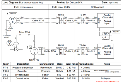
A P&ID shows the inter-relationships of the process piping, vessels, and instruments:

The purpose of this control system is to ensure the chemical solution inside the reactor vessel is maintained at a constant temperature. A steam-heated “jacket” envelops the reactor vessel, transferring heat from the steam into the chemical solution inside.
The control system maintains a constant temperature by measuring the temperature of the reactor vessel, and throttling steam from a boiler to the steam jacket to add more or less heat as needed.
We begin as usual with the temperature transmitter, located near the bottom of the vessel. Note the different line type used to connect the temperature transmitter (TT) with the temperature indicating controller (TIC): hollow diamonds with lines in between. This signifies a digital electronic instrument signal – sometimes referred to as a fieldbus – rather than an analog type (such as 4 to 20 mA ).
The transmitter in this system is actually a digital (fieldbus), and so is the controller. The transmitter reports the process variable (reactor temperature) to the controller using digital bits of information. Here there is no analog scale of 4 to 20 milliamps, but rather electric voltage/current pulses representing the 0 and 1 states of binary data.
Digital instrument signals are capable of transferring multiple data points rather than single data points as is the case with analog instrument signals. This means digital instrument signals may convey device status information (such as self-diagnostic test results) as well as the basic measurement value.
In other words, the digital signal coming from this transmitter not only tells the controller how hot the reactor is, but it may also communicate to the controller how well the transmitter is functioning.
The dashed line exiting the controller shows it to be analog electronic: most likely 4 to 20 milliamps DC. This electronic signal does not go directly to the control valve, however. It passes through a device labeled “TY”, which is a transducer to convert the 4 to 20 mA electronic signal into a 3 to 15 PSI pneumatic signal which then actuates the valve.
In essence, this signal transducer acts as an electrically-controlled air pressure regulator, taking the supply air pressure (usually 20 to 25 PSI) and regulating it down to a level commanded by the controller’s electronic output signal.
At the temperature control valve (TV) the 3 to 15 PSI pneumatic pressure signal applies a force on a diaphragm to move the valve mechanism against the restraining force of a large spring. The construction and operation of this valve is the same as for the feedwater valve in the pneumatic boiler water control system.
The letters “ATO” immediately below the valve symbol mean “AirTo-Open,” referring to the direction this valve mechanism will move (wider open) as more air signal pressure is applied to its actuator.
A detail not shown on this diagram, yet critically important to the operation of the temperature control system, is the direction of action for the controller while in automatic mode. It is possible to configure general-purpose controllers to act either in a direct fashion where an increasing process variable signal automatically results in an increasing output signal, or in a reverse fashion where an increasing process variable signal automatically results in a decreasing output signal.
An effective way to identify the proper direction of action for any process controller is to perform a “thought experiment ” whereby we imagine the process variable increasing over time, and then determine which way the controller’s output needs to change in order to bring the process variable value back to setpoint based on the final control element’s influence within the process.
In this process, let us imagine the reactor temperature increasing for some reason, perhaps an increase in the temperature of the feed entering the reactor. With an increasing temperature, the controller must reduce the amount of steam applied to the heating jacket surrounding the reactor in order to correct for this temperature change.
With an air-to-open (ATO) steam valve, this requires a decreased air pressure signal to the valve in order to close it further and reduce heat input to the reactor.
Thus, if an increasing process variable signal requires a decreasing controller output signal, the controller in this case needs to be configured for reverse action.
We could easily imagine reasons why the temperature controller in this process might have to be configured for direct action instead of reverse action. If the piping were altered such that the control valve throttled the flow of coolant to the reactor rather than steam, an increasing temperature would require a further-open valve, which would only happen if the controller were configured for direct action.
Alternatively, if the steam valve were air-to-close (ATC) rather than air-to-open (ATO), an increasing reactor temperature (requiring less steam be sent to the reactor) would necessitate the controller outputting an increased signal to the valve, so that more air signal pressure pushed the valve further closed.
Articles You May Like :
Setpoints and Alarms in System
How 4-20mA Transmitter Works ?