Inst ToolsInst ToolsInst Tools
  • Courses
  • Automation
    • PLC
    • Control System
    • Safety System
    • Communication
    • Fire & Gas System
  • Instrumentation
    • Design
    • Pressure
    • Temperature
    • Flow
    • Level
    • Vibration
    • Analyzer
    • Control Valve
    • Switch
    • Calibration
    • Erection & Commissioning
  • Interview
    • Instrumentation
    • Electrical
    • Electronics
    • Practical
  • Q&A
    • Instrumentation
    • Control System
    • Electrical
    • Electronics
    • Analog Electronics
    • Digital Electronics
    • Power Electronics
    • Microprocessor
  • Request
Search
  • Books
  • Software
  • Projects
  • Process
  • Tools
  • Basics
  • Formula
  • Power Plant
  • Root Cause Analysis
  • Electrical Basics
  • Animation
  • Standards
  • 4-20 mA Course
  • Siemens PLC Course
Reading: Zener Diode Barrier Principle
Share
Font ResizerAa
Inst ToolsInst Tools
Font ResizerAa
  • Courses
  • Design
  • PLC
  • Interview
  • Control System
Search
  • Courses
  • Automation
    • PLC
    • Control System
    • Safety System
    • Communication
    • Fire & Gas System
  • Instrumentation
    • Design
    • Pressure
    • Temperature
    • Flow
    • Level
    • Vibration
    • Analyzer
    • Control Valve
    • Switch
    • Calibration
    • Erection & Commissioning
  • Interview
    • Instrumentation
    • Electrical
    • Electronics
    • Practical
  • Q&A
    • Instrumentation
    • Control System
    • Electrical
    • Electronics
    • Analog Electronics
    • Digital Electronics
    • Power Electronics
    • Microprocessor
  • Request
Follow US
All rights reserved. Reproduction in whole or in part without written permission is prohibited.
Inst Tools > Blog > Control Systems > Zener Diode Barrier Principle

Zener Diode Barrier Principle

Last updated: June 22, 2019 12:47 pm
Editorial Staff
Control Systems
1 Comment
Share
3 Min Read
SHARE

The zener diode barrier works by diverting potentially dangerous energy to ground before it can reach the hazardous area.

Contents
Zener Diode Barrier PrincipleGrounding :

Zener Diode Barrier Principle

zener diode barrier

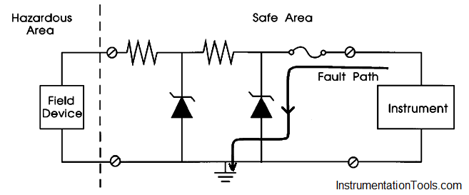
The zener diodes limit the fault voltage to the hazardous area. There are two such diodes for redundancy. The series resistor limits current to the hazardous area, and is considered an infallible component.

The arrow in above Figure  shows the resultant path if excess current enters the barrier as a result of excess voltage input from the instrument.

Since a zener barrier is powered by the loop and it has a current limiting resistor, it has a voltage drop across it. This barrier, in addition to protecting against dangerous energy entering the hazardous area, must allow the loop to function normally.

Example :

The example in Below Figure, shows a 24 V, 4-20 mA transmitter loop. In this example, the sum of the voltage drops around the loop can be calculated and verified that they are less than 24 V.

Instead, since the maximum resistance of the barrier is specified (RMAX END TO END), Ohm’s law is used (V = IR) to calculate the total resistance available in the loop. Either method (loop voltage or loop resistance) works identically.

What we are trying to decide is whether or not the resistance of the barrier will adversely affect the loop.

Zener Barrier Protection

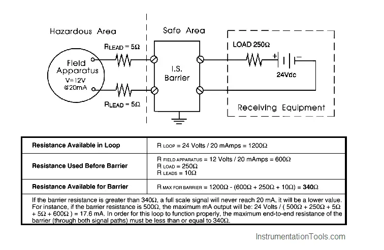
Resistance of zener barrier adversely affects this 24V, 4-20mA transmitter loop ? Not, if it is less than 340 Ω

Grounding :

When using zener barriers, the dangerous energy is diverted to ground. Therefore, it is important to ensure a high quality intrinsic safety ground.

In fact, because this grounding is so critical, two separate ground connections from each barriers are recommended, each with a resistance of less than 1 ohm.

The following rules should be adhered to for I.S. grounding:

  1. Since zener diode barriers work by diverting fault currents, they must have a good quality ground.
  2. The impedance of the conductor from the barrier ground bus to the ground connection should be less than 1 ohm.
  3. Follow local codes.
  4. Ground cables should be insulated.
  5. Ground cables should be protected mechanically if there is a risk of damage.
  6. Ground cable should be an uninterrupted run to the nearest high integrity earth point.
  7. Redundant cables are advisable.
Don't Miss Our Updates
Be the first to get exclusive content straight to your email.
We promise not to spam you. You can unsubscribe at any time.
Invalid email address
You've successfully subscribed !

Continue Reading

Liquid Level Switch Control Pump and Lamp
Design and Implement Motor Control – Electrical Engineering
Free PID Controller Gains Tuning Tool
Grounding or Earthing Scheme in DCS or PLC Systems
What LIC and FIC Controllers will do?
Chemical Reactor Temperature Control System
Share This Article
Facebook Whatsapp Whatsapp LinkedIn Copy Link
Share
1 Comment
  • Gregory Dwyer says:
    July 3, 2025 at 9:48 pm

    Great write up!

    Reply

Leave a Reply Cancel reply

Your email address will not be published. Required fields are marked *

Stay Connected

128.3kFollowersLike
69.1kFollowersFollow
210kSubscribersSubscribe
38kFollowersFollow

Categories

Explore More

Vendor Document for Project Systems Architecture
Add On Instructions Programming – Analog Input Devices in Studio 5000
Difference between ON-OFF Controller and PID Controller
Recognizing a Porpoising PID Controller
Explaining Various Types of Analog Instruments
Difference Between SCADA and HMI
PID Controller Parameters Tuning Manually
Industrial Automation in the Mining Industry

Keep Learning

Interlock

Process Interlocks and Trips

Remote Factory Acceptance Test

Remote Factory Acceptance Test

BACNet Protocol

What is the BACNet Protocol? BACNet IP vs. BACNet MS/TP

Level Control Loop Principle

Integrating Processes – Liquid Level Control

Process Control Instrumentation Terms Glossary

Process Control Instrumentation Glossary

Loop Power Indicator Principle

Basics of Loop Powered Devices

PID Controller Functionality

PID Controller Loop Tuning Tips

Flexible Input Output Modules

Flexible Input Output Modules

Learn More

Moving Coil Type Velocity Transducer

Moving Coil Type Velocity Transducer

Interlock

Process Interlocks and Trips

progressively sequenced control valves

Progressive Control Valve Sequence

P&ID Legend

What is a Legend? – Piping and Instrumentation Diagram

Safety Questions and Answers

Safety Questions and Answers

Variable Air Volume Controller in HVAC

What is Variable Air Volume Controller in HVAC?

Control Valves Quiz

Interactive Control Valve Parts Quiz: Drag & Drop Challenge

Difference between Transmitter and Transducer with Examples

Difference between Transmitter and Transducer with Examples

Menu

  • About
  • Privacy Policy
  • Copyright

Quick Links

  • Learn PLC
  • Helping Hand
  • Part Time Job

YouTube Subscribe

Follow US
All rights reserved. Reproduction in whole or in part without written permission is prohibited.
Welcome Back!

Sign in to your account

Username or Email Address
Password

Lost your password?