Inst ToolsInst ToolsInst Tools
  • Courses
  • Automation
    • PLC
    • Control System
    • Safety System
    • Communication
    • Fire & Gas System
  • Instrumentation
    • Design
    • Pressure
    • Temperature
    • Flow
    • Level
    • Vibration
    • Analyzer
    • Control Valve
    • Switch
    • Calibration
    • Erection & Commissioning
  • Interview
    • Instrumentation
    • Electrical
    • Electronics
    • Practical
  • Q&A
    • Instrumentation
    • Control System
    • Electrical
    • Electronics
    • Analog Electronics
    • Digital Electronics
    • Power Electronics
    • Microprocessor
  • Request
Search
  • Books
  • Software
  • Projects
  • Process
  • Tools
  • Basics
  • Formula
  • Power Plant
  • Root Cause Analysis
  • Electrical Basics
  • Animation
  • Standards
  • 4-20 mA Course
  • Siemens PLC Course
Reading: Working Principle of Pressure Gauge
Share
Notification Show More
Font ResizerAa
Inst ToolsInst Tools
Font ResizerAa
  • Courses
  • Design
  • PLC
  • Interview
  • Control System
Search
  • Courses
  • Automation
    • PLC
    • Control System
    • Safety System
    • Communication
    • Fire & Gas System
  • Instrumentation
    • Design
    • Pressure
    • Temperature
    • Flow
    • Level
    • Vibration
    • Analyzer
    • Control Valve
    • Switch
    • Calibration
    • Erection & Commissioning
  • Interview
    • Instrumentation
    • Electrical
    • Electronics
    • Practical
  • Q&A
    • Instrumentation
    • Control System
    • Electrical
    • Electronics
    • Analog Electronics
    • Digital Electronics
    • Power Electronics
    • Microprocessor
  • Request
Follow US
All rights reserved. Reproduction in whole or in part without written permission is prohibited.
Inst Tools > Blog > Animation > Working Principle of Pressure Gauge

Working Principle of Pressure Gauge

Last updated: September 13, 2017 7:22 am
Editorial Staff
Animation How It Works Pressure Measurement
1 Comment
Share
3 Min Read
SHARE

The Bourdon pressure gauge uses the principle that a flattened tube tends to straighten or regain its circular form in cross-section when pressurized.

bourdon-tube-pressure-gauge-working-animation

Although this change in cross-section may be hardly noticeable, and thus involving moderate stresses within the elastic range of easily workable materials, the strain of the material of the tube is magnified by forming the tube into a C shape or even a helix, such that the entire tube tends to straighten out or uncoil, elastically, as it is pressurized.

In practice, a flattened thin-wall, closed-end tube is connected at the hollow end to a fixed pipe containing the fluid pressure to be measured. As the pressure increases, the closed end moves in an arc, and this motion is converted into the rotation of a (segment of a) gear by a connecting link that is usually adjustable.

Pressure Gauge Operation Animation

A small-diameter pinion gear is on the pointer shaft, so the motion is magnified further by the gear ratio. The positioning of the indicator card behind the pointer, the initial pointer shaft position, the linkage length and initial position, all provide means to calibrate the pointer to indicate the desired range of pressure for variations in the behavior of the Bourdon tube itself.

Differential pressure can be measured by gauges containing two different Bourdon tubes, with connecting linkages.
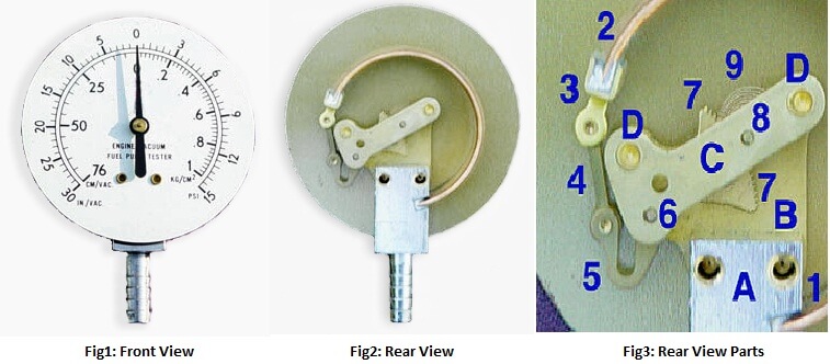
Mechanical details

Stationary parts:

  • A: Receiver block. This joins the inlet pipe to the fixed end of the Bourdon tube (1) and secures the chassis plate (B). The two holes receive screws that secure the case.
  • B: Chassis plate. The face card is attached to this. It contains bearing holes for the axles.
  • C: Secondary chassis plate. It supports the outer ends of the axles.
  • D: Posts to join and space the two chassis plates.

pressure-gauge-internal-parts-animation

Moving Parts:

  1. Stationary end of Bourdon tube. This communicates with the inlet pipe through the receiver block.
  2. Moving end of Bourdon tube. This end is sealed.
  3. Pivot and pivot pin.
  4. Link joining pivot pin to lever (5) with pins to allow joint rotation.
  5. Lever. This is an extension of the sector gear (7).
  6. Sector gear axle pin.
  7. Sector gear.
  8. Indicator needle axle. This has a spur gear that engages the sector gear (7) and extends through the face to drive the indicator needle. Due to the short distance between the lever arm link boss and the pivot pin and the difference between the effective radius of the sector gear and that of the spur gear, any motion of the Bourdon tube is greatly amplified. A small motion of the tube results in a large motion of the indicator needle.
  9. Hair spring to preload the gear train to eliminate gear lash and hysteresis.

pressure-gauge-internal-parts

Also Read: Working Principle of Rotameters

Don't Miss Our Updates
Be the first to get exclusive content straight to your email.
We promise not to spam you. You can unsubscribe at any time.
Invalid email address
You've successfully subscribed !

Continue Reading

Stepper Motor Working Principle
Pressure Transmitters Heat-traced impulse lines
Information on the Pressure Gauge Dial
What is Seal-in Circuit ?
Instrument Protection Methods: Seals
Optical Pyrometer Working Principle Animation
Share This Article
Facebook Whatsapp Whatsapp LinkedIn Copy Link
Share
1 Comment
  • Samuel G Kukako says:
    March 30, 2021 at 2:25 pm

    I WANT MORE DIAGRAMITIC RESPRESSENTION AND SPECIFIC WORKING PRINCIPLES IN DETAIL OF A PRESSURE GAUGE

    Reply

Leave a Reply Cancel reply

Your email address will not be published. Required fields are marked *

Stay Connected

128.3kFollowersLike
69.1kFollowersFollow
210kSubscribersSubscribe
38kFollowersFollow

Categories

Explore More

Deluge Valve Operation
Tilt Level Switch Working Animation
Basics of Gate Valves
Magnetic Level Indicators Working Animation
Understanding the Scan Cycle of SIEMENS PLC
Installation and Calibration of Pressure Transmitter
Bourdon Tube Pressure Gauge Working Principle Animation
Network Switch Port Allocation Details

Keep Learning

Level-Transmitters-Animation

Level Transmitter Animation

Argonite/CO2 Flooding System Master & Slave Cylinder Operation

Anti Surge Controller Theory

Anti Surge Controller Working Principle

Pressure Measurement using Manometer

Pressure Measurement using Manometer

Uncertainty Calculations of Pressure Calibration

Uncertainty Calculations of Pressure Calibration

Capacitance Pressure Sensor Principle

Electronic Pressure Sensors Principle

Motor contactors

What is Contactor ?

Rotameters Working

Rotameter Working Principle and Animation

Learn More

How to Identify the Transistor Terminals

Field Transmitter Installation

Cables and Cable Glands Questions and Answers

Motor STAR - DELTA Working principle

Motor STAR – DELTA Starter Working Principle

Faceplate in WinCC

Siemens HMI Training – Using UDTs with Faceplates

Power Electronics Objective Questions

Quiz on Thyristor Chopper

LogixPro Simulator Software

Introducing PLC Programming using LogixPro Simulator Software

Count the Number of Cartons in a Storage Area PLC Logic

Count the Number of Cartons in a Storage Area PLC Logic

Temperature Measurement Multiple Choice Questions

Temperature Measurement Multiple Choice Questions

Menu

  • About
  • Privacy Policy
  • Copyright

Quick Links

  • Learn PLC
  • Helping Hand
  • Part Time Job

YouTube Subscribe

Follow US
All rights reserved. Reproduction in whole or in part without written permission is prohibited.
Welcome Back!

Sign in to your account

Username or Email Address
Password

Lost your password?