Inst ToolsInst ToolsInst Tools
  • Courses
  • Automation
    • PLC
    • Control System
    • Safety System
    • Communication
    • Fire & Gas System
  • Instrumentation
    • Design
    • Pressure
    • Temperature
    • Flow
    • Level
    • Vibration
    • Analyzer
    • Control Valve
    • Switch
    • Calibration
    • Erection & Commissioning
  • Interview
    • Instrumentation
    • Electrical
    • Electronics
    • Practical
  • Q&A
    • Instrumentation
    • Control System
    • Electrical
    • Electronics
    • Analog Electronics
    • Digital Electronics
    • Power Electronics
    • Microprocessor
  • Request
Search
  • Books
  • Software
  • Projects
  • Process
  • Tools
  • Basics
  • Formula
  • Power Plant
  • Root Cause Analysis
  • Electrical Basics
  • Animation
  • Standards
  • 4-20 mA Course
  • Siemens PLC Course
Reading: Why we use Diode Protection Modules ?
Share
Font ResizerAa
Inst ToolsInst Tools
Font ResizerAa
  • Courses
  • Design
  • PLC
  • Interview
  • Control System
Search
  • Courses
  • Automation
    • PLC
    • Control System
    • Safety System
    • Communication
    • Fire & Gas System
  • Instrumentation
    • Design
    • Pressure
    • Temperature
    • Flow
    • Level
    • Vibration
    • Analyzer
    • Control Valve
    • Switch
    • Calibration
    • Erection & Commissioning
  • Interview
    • Instrumentation
    • Electrical
    • Electronics
    • Practical
  • Q&A
    • Instrumentation
    • Control System
    • Electrical
    • Electronics
    • Analog Electronics
    • Digital Electronics
    • Power Electronics
    • Microprocessor
  • Request
Follow US
All rights reserved. Reproduction in whole or in part without written permission is prohibited.
Inst Tools > Blog > Control Systems > Why we use Diode Protection Modules ?

Why we use Diode Protection Modules ?

Last updated: March 18, 2019 10:43 am
Editorial Staff
Control Systems Instrumentation Design
6 Comments
Share
5 Min Read
SHARE

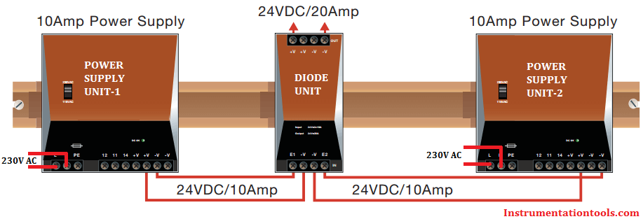
The Diode module can be used to 100% decouple two power supplies of the same type, which are connected in parallel on the output side to increase power or provide redundancy.

Diode protection for a DC power supply is a critical piece of a control system.  Power supply failure can lead to a process shutting down resulting in considerable lost revenue.

To prevent unplanned shutdowns users often use redundant power supplies, i.e. power supplies with their outputs connected in parallel, where if one supply fails there are enough remaining power supplies to deliver the required load current.

Diode Protection Modules

Power Supply Unit with Diode Protection

Redundant power supplies can be also be used for increased current capacity – in this case the concern is less about unplanned shutdowns but rather the fact one supply cannot deliver the load current required.

For increased current capacity power supplies with “active load sharing” are preferred.  This involves the power supplies communicating with each other and adjusting their output voltages so that each supply delivers the same current.

If two supplies are used each one will deliver half the required current.  If three supplies are used each one delivers a third of the total current required.

Without active load sharing each power supply must be adjusted so that their output voltages are identical, they much be maintained at the same ambient temperature and the wiring between each power supply and the common point should be of equal lengths – all difficult conditions to maintain.

Redundant Power Supply with O-ring Diode

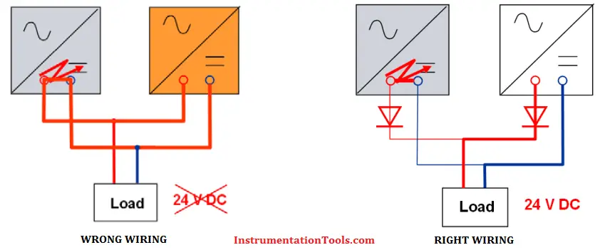
Regardless of the reason for using redundant power supplies it is common practice to provide diode protection in series with the output of each power supply so a failed power supply cannot draw current from any operating power supplies.

If there is a short circuit in the output of a power supply that unit will shutdown but it could also short circuit any power supplies connected in parallel causing those to shutdown as well.

A diode on the output of each supply prevents this from happening.

Diode Protection for 24v Power Supply unit

Using diodes to isolate power supplies, often referred to as “ORing diodes”, has the disadvantage of increasing power dissipation within the control cabinet.

A typical diode drops the voltage 0.7V when conducting a current.  This means 0.7W per amp of load current.  If two redundant power supplies are delivering a total of 10A then the diodes will dissipate 7W in the cabinet.  Using Schottky diodes could lower the power dissipation to approximately 4W.

Either way, this power dissipation is unwanted and increases the ambient temperature within the cabinet.  Sometimes bridge rectifiers are used because they are relatively inexpensive, are designed for high power dissipation, and can be mounted directly on the wall of the cabinet so that the cabinet acts as a heat sink.

Redundant Power Supply Units Wiring

Reliability is a concern (or should be) when using ORing diodes.  If a diode fails in a short circuited state then there is no protection and the voltage from that supply appears to increase by 0.7V.

Unless active load sharing is used that supply may try to deliver the total load current.  If the power supplies are connected in parallel for increased current capacity then the supply might go in to an overcurrent condition and shutdown.

If one of the ORing diodes fails in an open circuit state then there is no longer any redundancy and a shutdown of thr remaining power supply could occur.

An option is to use an active diode circuit.  These are based on using a MOSFET, with additional circuitry, in place of the diode.  MOSFET’s have the advantage of a very low on-state resistance meaning the power dissipation is reduced significantly.

For example, at 10A a diode will dissipate 7W while the MOSFET based active diode circuit can dissipate as little as 0.4W.  Obviously this produces a lower ambient temperature within the cabinet and also offers greater reliability.

Also Read: Pull Up and Pull Down Switch

Don't Miss Our Updates
Be the first to get exclusive content straight to your email.
We promise not to spam you. You can unsubscribe at any time.
Invalid email address
You've successfully subscribed !

Continue Reading

Foundation Fieldbus Installation and Best Practices
Problem in Water Level Control System
Types of Cable Trays – Purpose, Advantages, Disadvantages
Using of MCT instead of Cable Glands on the Cabinets
What is a Surge Protection Device? – Principle, Types, Advantages
Instrumentation and Control (I&C) Design
Share This Article
Facebook Whatsapp Whatsapp LinkedIn Copy Link
Share
6 Comments
  • Sachin says:
    March 20, 2016 at 2:03 am

    Good Article

    Reply
  • ajit Kumar says:
    March 21, 2016 at 7:22 am

    thanks

    Reply
  • Rajiv Kumar says:
    November 16, 2016 at 6:32 am

    I have heard that once a diode oring is implemented, load sharing between power supplies do not work. I am not able to correlate this or find any data which supports this statement. Can anyone help me out to say if this is true or not?

    Reply
  • NAVEED IQBAL says:
    September 1, 2017 at 5:28 am

    There is one more instruments site can someone upload the link that is Instreng.co.in something like this where there is good information.Thanks

    Reply
    • S Bharadwaj Reddy says:
      September 1, 2017 at 6:17 am

      Instreng.com is a community platform for instrumentation engineers, very knowledgeable source. Few months ago it was hacked and now we missed it a lot. Recently Inst Tools also hacked & luckily i have a backup of the website & immediately restored. Hope everything will be fine.

      Reply
  • Dattu Vemana says:
    August 5, 2021 at 8:56 pm

    Sir, please post about field interfere module. D

    Reply

Leave a Reply Cancel reply

Your email address will not be published. Required fields are marked *

Stay Connected

128.3kFollowersLike
69.1kFollowersFollow
210kSubscribersSubscribe
38kFollowersFollow

Categories

Explore More

How to Calculate Heat Load in Electrical/Electronic Panel Enclosure
Basic Concepts of the Safety Relay
What is Alarm Management System ?
Process Design of Instrument Air System
Industry 4.0
ICS System Design Considerations
Industrial Automation Mobile Apps
Direct Digital Control (DDC) Systems

Keep Learning

Pressure Gauge Datasheet

How to Fill up Instrument Datasheet? – Pressure Gauge Specifications & Standards

Instrument Loop Diagram

How-to Create Instrument Loop Diagram (ILD)?

O Ring Failure

How O-Ring Failure caused NASA’s shuttle to Blast ?

SCADA Systems

SCADA Systems

Grounding Components

Selection of Components Used In Electrical Earthing or Grounding

How Engineers Effectively do Problem-solve and Troubleshoot

How Engineers Effectively do Problem-solve and Troubleshoot?

Load Cell Design

How to select a load cell?

Advantages of Redundant System

Redundant Automation Systems – Need and Advantages

Learn More

Power Electronics Objective Questions

Power Transistor Objective Questions

Magnetic Float Level Sensor Principle

Magnetic Float Level Transmitter Working Principle

Power Electronics Objective Questions

Sequence Controller Objective Questions

memory types in siemens plc

#13 PLC Best Practices – Disable Unused Communication Ports

Liquid Nitrogen in Instrumentation

Liquid Nitrogen in Instrumentation

Problem on Solar Hot Air Collector and Variable Speed Fan

Problem on Solar Hot Air Collector and Variable Speed Fan

Characteristics of Protective Relay

What is a Protective Relay? Principle, Advantages, Applications

Tips to Maintain & Extend the Life of CNC Tools

Tips for Maintaining and Extending the Life of Your CNC Tools

Menu

  • About
  • Privacy Policy
  • Copyright

Quick Links

  • Learn PLC
  • Helping Hand
  • Part Time Job

YouTube Subscribe

Follow US
All rights reserved. Reproduction in whole or in part without written permission is prohibited.
Welcome Back!

Sign in to your account

Username or Email Address
Password

Lost your password?