Inst ToolsInst ToolsInst Tools
  • Courses
  • Automation
    • PLC
    • Control System
    • Safety System
    • Communication
    • Fire & Gas System
  • Instrumentation
    • Design
    • Pressure
    • Temperature
    • Flow
    • Level
    • Vibration
    • Analyzer
    • Control Valve
    • Switch
    • Calibration
    • Erection & Commissioning
  • Interview
    • Instrumentation
    • Electrical
    • Electronics
    • Practical
  • Q&A
    • Instrumentation
    • Control System
    • Electrical
    • Electronics
    • Analog Electronics
    • Digital Electronics
    • Power Electronics
    • Microprocessor
  • Request
Search
  • Books
  • Software
  • Projects
  • Process
  • Tools
  • Basics
  • Formula
  • Power Plant
  • Root Cause Analysis
  • Electrical Basics
  • Animation
  • Standards
  • 4-20 mA Course
  • Siemens PLC Course
Reading: Why Fiber Optic Cable is Spliced rather than Termination?
Share
Notification Show More
Font ResizerAa
Inst ToolsInst Tools
Font ResizerAa
  • Courses
  • Design
  • PLC
  • Interview
  • Control System
Search
  • Courses
  • Automation
    • PLC
    • Control System
    • Safety System
    • Communication
    • Fire & Gas System
  • Instrumentation
    • Design
    • Pressure
    • Temperature
    • Flow
    • Level
    • Vibration
    • Analyzer
    • Control Valve
    • Switch
    • Calibration
    • Erection & Commissioning
  • Interview
    • Instrumentation
    • Electrical
    • Electronics
    • Practical
  • Q&A
    • Instrumentation
    • Control System
    • Electrical
    • Electronics
    • Analog Electronics
    • Digital Electronics
    • Power Electronics
    • Microprocessor
  • Request
Follow US
All rights reserved. Reproduction in whole or in part without written permission is prohibited.
Inst Tools > Blog > Communication > Why Fiber Optic Cable is Spliced rather than Termination?

Why Fiber Optic Cable is Spliced rather than Termination?

Splicing refers to the method of connecting two fiber optic cables and termination is used to connect two cables.

Last updated: August 3, 2023 4:03 pm
Editorial Staff
Communication
No Comments
Share
3 Min Read
SHARE

Splicing refers to the method of connecting two fiber optic cables and termination is used to connect two cables. Let’s explore the differences between the two, and why splicing is generally preferred over termination in fiber optic cables.

Contents
SplicingTerminationWhy Splicing Instead of Termination?

Splicing

Splicing is a process that permanently joins two optical fibers end-to-end, creating a continuous optical path. The goal is to ensure that the light passing through the fibers continues with as little loss or reflection as possible.

There are two main methods of splicing:

  1. Fusion Splicing: This involves using an electric arc or laser to melt the ends of the optical fibers together. It provides a very low-loss connection, and when done correctly, the splice may be almost as strong as the original fiber.
  2. Mechanical Splicing: This involves aligning the fiber ends and holding them together using an adhesive or mechanical clamp. It is generally quicker but may have a higher loss and less mechanical strength compared to fusion splicing.
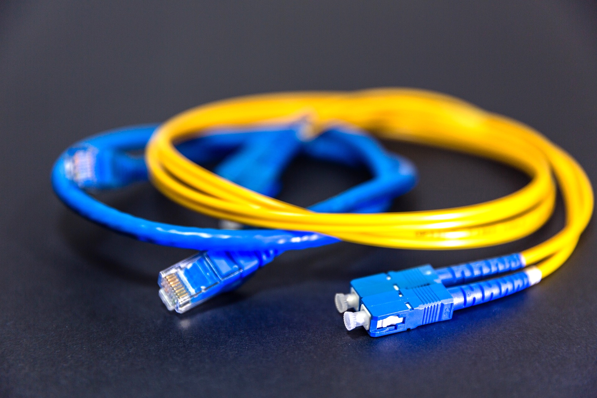
Why Fiber Optic Cable is Spliced rather than Termination

Termination

Termination (Jointing, Joining, or connecting) word is typically used in connecting copper cables (or other materials). We never use the word termination in fiber optics as they do not create a permanent connection.

If the termination method is used in fiber optics, it typically involves higher loss compared to splicing, as the fibers are not fused together and there may be a small air gap or mismatch between the fibers. This leads to reflection and scattering of the light signal and leads to signal loss.

Why Splicing Instead of Termination?

Splicing is generally preferred over termination for the following reasons:

  1. Lower Loss: Splicing, especially fusion splicing, provides a lower loss connection, ensuring a more efficient transmission of the optical signal.
  2. Permanent Connection: Splicing creates a permanent bond between the fibers, providing greater mechanical strength and reliability.
  3. No Reflection: Properly spliced fibers have no air gap or mismatch at the junction, minimizing reflection and potential interference with the signal.
  4. Cost-Effective in the Long Run: While splicing equipment may be expensive, the low loss and reliability of spliced connections can make it more cost-effective in the long run for certain applications like long-haul transmission.

So, for fiber-optic cables, splicing is the preferred method due to its low loss and reliability.

Read Next:

  • Instrumentation Engineering Quiz
  • Electrical Control Devices Questions
  • Transducers Objective Questions
  • Flow and Level Measurement Quiz
  • Circuit Protection Devices Questions
Don't Miss Our Updates
Be the first to get exclusive content straight to your email.
We promise not to spam you. You can unsubscribe at any time.
Invalid email address
You've successfully subscribed !

Continue Reading

Fieldbus Transmitters Calibration and Ranging
Layer-2 and Layer-3 Network Switches
Foundation Fieldbus Logics
Fieldbus Coupling Devices
Difference Between Serial and Parallel Communication
Serial Communication Interview Questions and Answers
Share This Article
Facebook Whatsapp Whatsapp LinkedIn Copy Link
Share
Leave a Comment

Leave a Reply Cancel reply

Your email address will not be published. Required fields are marked *

Stay Connected

128.3kFollowersLike
69.1kFollowersFollow
210kSubscribersSubscribe
38kFollowersFollow

Categories

Explore More

Difference between Router, Switch, and Hub
WirelessHART Network Gateway Device
HART Communication Protocol Overview
Fiber Optic Data Communication
What is a Patch Panel? Types and Uses in Networking
Serial Communication Data Transmission Modes
OPC Communication Interview Questions and Answers
How Profibus Communication Works

Keep Learning

fieldbus cables layout

H1 FF Data Link layer

How to Calculate Network Speed?

Factors to Consider When Calculating Network Speed

Switches, Repeaters, Bridges, Routers, Firewalls

Purpose of Gateways, Bridges & Routers in Networking

WirelessHART Principle

Wireless HART Communication Protocol Overview

Modbus scan

How Modbus Communication works

Fiber Optic Patch Cord

What is a Fiber Optic Patch Cord? – Types, Explained

Input function blocks

FF Function Blocks

Optical Fiber Size

Fiber Optic Cable Connectors, Routing, and Safety

Learn More

Motor STAR - DELTA Working principle

Motor STAR – DELTA Starter Working Principle

Left-hand Rule for Current Carrying Conductors

Magnetism

Infrared Flue Gas Analyser

What is Infrared Flue Gas Analyzer? – Working Principle

WirelessHART Principle

Wireless HART Communication Protocol Overview

Control Valve Passing Problem after Overhauling Job

Control Valve Passing Problem after Overhauling Job

Barrier & Sensor Connection with NAMUR

Why we use NAMUR Output Sensor?

Cable Float Level Switch Principle

Cable Float Level Switch Working Principle

Difference Between PNP and NPN Sensors

Difference Between PNP and NPN Sensors

Menu

  • About
  • Privacy Policy
  • Copyright

Quick Links

  • Learn PLC
  • Helping Hand
  • Part Time Job

YouTube Subscribe

Follow US
All rights reserved. Reproduction in whole or in part without written permission is prohibited.
Welcome Back!

Sign in to your account

Username or Email Address
Password

Lost your password?