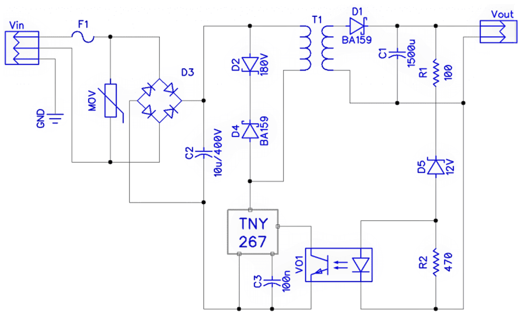
Switch Mode Power Supply (SMPS) works by converting high AC voltage into DC power using a transformer, rectifier, MOSFET transistor, as seen on Linear Power Supply (LPS).
In essence, it is ideal for providing an additional layer of protection through isolation devices to be included in SMPS.
Isolators are devices used to isolate a particular circuit or equipment from a known power source. It serves as a mechanical switch that allows manipulation of both input and output power sources coming in from an open position and isolates both circuits.
Switch Mode Power Supply
In equipment component failure, isolation serves as a physical barrier to potentially dangerous voltages. By using isolation mechanisms, electric shock and fire hazards are prevented.
An isolated power supply creates a power output that is electrically independent of its input power. When multiple isolated power outputs are used, the output voltage generated is then independent of one another with relatively no connection in between. Several reasons why switch mode power supply needs isolation include:
Safety Promotion
User safety and device efficiency are fundamental considerations in selecting power supply outputs. Power supplies that have isolation properties are needed in AC supply voltage conversion.
Isolation prevents the main AC voltage from crossing the output gradient, thus preventing equipment malfunction. SMPS uses optoisolators to measure the output voltage created to regulate the power output and further promote system safety.
Also, isolation separates potentially dangerous voltages flowing in from converters powered by high voltages coming from AC mains acting as its primary input, thus promoting user and equipment safety.
Prevention of Ground Loops
Isolated power supplies prevent the occurrence of ground loops. Ground loops occur when multiple circuits share a single return path.
The current flowing from this ground loop can cause one or multiple courses to malfunction, causing a break in the system. It results in signal noise, communication errors, and damage to the flow of ground current and long cables.
Isolated power supplies help prevent loops from occurring and maintain system integrity even with multiple circuits present.
Equipment protection
SMPS with isolation helps protect equipment from power conduction line-level events such as lightning strikes, electric surges, etc.
Proper insulation of electric pathways is also used to safeguard electrical circuits further.
Flexibility and Efficiency
System flexibility occurs when power supplies come with multiple isolated outputs.
These allow isolated power supplies to be easily connected to create a higher power voltage or be placed in parallel arrangement to yield higher output currents.
This is also termed voltage level shifting.
Key Takeaways
SMPS converts high voltage AC input to DC output without using a transformer. It utilizes MOSFET transistors and other electrical components during AC/DC conversion.
The use of isolation is a measure that safeguards the equipment from potential electric surges. It also promotes user safety by eliminating electric shocks during breaks in the component integrity.
Isolation removes ground loops from occurring which reduces equipment functionality and efficiency.
The inclusion of isolators in SMPS creates greater flexibility through voltage level shifting, allowing multiple isolated outputs to be connected to yield a high-power voltage or be tacked in parallel to produce a higher output current.