Redundancy is designed to make system transitions seamless, but many automation engineers are surprised when switchover doesn’t happen cleanly. The most common reason is imperfect synchronization; even a tiny mismatch in I/O images, internal buffers, or sequence states can prevent the standby controller from taking over. Another hidden cause is network latency on the redundancy link; a momentary delay in heartbeat packets can break the switchover logic.
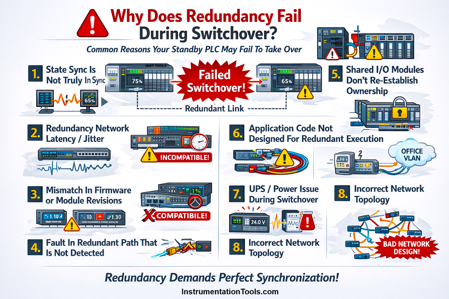
PLC Redundancy Fails During Switchover
Firmware mismatches, slow I/O ownership reassignment, or non-redundant internal tags in the logic also lead to failures. In some cases, both CPUs briefly think they are primary (“split-brain”), forcing a shutdown. In short, redundancy fails not because the hardware is weak, but because true switchover requires perfect timing, identical runtime states, and a clean network path, conditions that are rarely perfect in real plants. In this post, we will see why redundancy fails during switchover many times.
Before proceeding, let us first understand how data flows from primary to secondary systems. In a redundant PLC system, the primary controller constantly streams its live runtime data to the secondary over a dedicated redundancy link. Even though both PLCs have the same program, their internal values change every scan, so the primary keeps sending updated I/O images, tag values, timers, counters, PID internal states, and communication buffers to the standby.
The secondary does not run independently; instead, it stays in a synchronized mode where it mirrors the primary’s internal memory by continuously receiving these updates and overwriting its own data to stay identical. This rapid, cycle-by-cycle data transfer ensures that if the primary fails, the secondary already holds the exact same state and can take over immediately without any jump or disturbance. Let us now see some possible failure causes of redundancy during switching.
State synchronization is not truly in sync
Even though the primary continuously updates the secondary, perfect synchronization is hard to achieve in real plants. When the standby does not exactly mirror the primary, several issues can appear during switchover. If the standby has slightly older output values updated just a few milliseconds ahead in the primary one, taking over suddenly can cause motors, valves, or lamps to jump to the wrong states.
A networked device may miss a command that was in-flight during switchover. PID loops rely on precise internal states. If the standby’s internal integral/differential values are lagging, the loop can temporarily overshoot or undershoot. Event queues may not fully match, so the operator sees inconsistent alarms after switchover. Some controllers detect data mismatch during switchover and force a STOP or fault to prevent unsafe operation.
In short, even a few milliseconds or missing micro-states can make a supposedly “synchronized” standby fail to take over cleanly.
Redundancy network latency
In redundant PLC systems, the primary and secondary stay synchronized through a dedicated redundancy network, usually a high-speed Ethernet link or backplane channel. This link carries heartbeat signals, state updates, I/O images, and synchronization packets every few milliseconds.
If the redundancy network experiences latency (delay) or jitter (unstable, varying delay), the standby PLC receives the primary’s updates late, out-of-order, or sometimes not at all. Even a delay of just 20–30 ms can cause the standby to fall a scan behind, creating an “almost but not fully synchronized” condition.
In severe cases, the heartbeat packets time out, making each PLC think the other is offline, leading to a failed switchover or even a split-brain scenario. This kind of latency usually happens due to bad switches, overloaded VLANs, long fibre paths, poorly designed network topology, or momentary packet loss. Since redundancy depends on continuous, real-time data flow, even minor jitter can break the reliability of switchover.
Mismatch in firmware or module revisions
Redundant PLCs must behave like two identical twins, not just in program logic but also in firmware, hardware revisions, and module versions. If the primary and secondary PLCs run different firmware versions, use I/O cards with different hardware revisions, or have uneven communication module updates, their internal runtime behaviors will not match exactly, even if the program is the same.
In redundancy, the primary sends specific sync packets that the secondary must decode using the same firmware logic. When versions differ, the secondary may misinterpret those packets, skip certain data fields, or reject updates entirely. This leads to partial synchronization, constant “sync in progress” status, or a complete failure to assume the primary role during a switchover.
Even small differences like minor firmware patches, EDS versions, or module bootloaders can break redundancy because timing, packet structure, or buffer mapping changes subtly. That is why vendors strictly require identical firmware, identical module types, identical revisions, and often even identical SD card images on both sides for stable redundancy.
Shared IO modules do not reestablish ownership
In many redundant PLC architectures, the field I/O adapters (EtherNet/IP, Profibus, Profinet, DeviceNet, etc.) allow only one PLC at a time to be the owner of the I/O. During normal operation, the primary PLC owns all I/O connections, and the secondary stays in standby mode without controlling those modules.
During a switchover, the standby must quickly:
- Detect that the primary has failed
- Request ownership of each I/O module
- Establish new cyclic connections
- Start scanning the input/output data
This process must happen in a few milliseconds.
If any I/O module:
- responds slowly,
- has long connection timeout settings,
- is busy re-establishing a previous connection,
- or requires manual “release” from the old primary,
Then the standby cannot take ownership fast enough. As a result:
- Some I/O modules remain unowned
- Outputs stay frozen or go to fail-safe
- Inputs may not update
- The switchover becomes incomplete or fails entirely
This is especially common in:
- EtherNet/IP adapters that take time to close old connections
- Profinet devices with slow AR (Application Relationship) rebuild times
- Profibus DP/DPV1 modules needing token reassignments
- Redundant ring networks are still converging
In short, redundancy is not just controller-to-controller; the field I/O must also agree to switch owners, and if they can’t do it fast enough, switchover breaks.
Application code not designed for redundant execution
Even if the hardware redundancy is perfect, the logic inside the PLC must also be written to support redundancy. Most failures happen because the program was designed for a single PLC system, not for a dual-processor redundant environment.
Many internal variables used in sequences, timers, counters, interlocks, and PID blocks are not automatically synchronized by the redundancy system. If the programmer stores critical states in non-redundant memory areas, the primary and standby will never match these values perfectly. So when switchover happens, the standby may jump to a different step, reset timers, or activate outputs incorrectly.
Typical coding mistakes that break redundancy:
- Using temporary tags (non-retentive) for critical steps
- Not marking data blocks as “redundant memory” (Siemens) or “non-volatile” (Rockwell)
- Using scan-based logic that behaves differently on two CPUs
- ST/FB logic that writes different values based on timestamp, comm status, or scan time
- Storing PID internal values (integral output, last error) in non-synced tags
- Using clock-based pulses that don’t match between CPUs
- Relying on communication instructions that behave differently in standby mode
Because of these issues, the standby PLC is technically synchronized, but logically not ready to continue from the exact same state. During switchover, this causes incorrect outputs, halted sequences, or a complete failover fault.
Power issue during switchover
Redundant PLC systems assume that when the primary fails, the standby remains completely stable and powered. But in many plants, both PLCs, their switches, and even their I/O racks are fed through the same UPS, the same power panel, or the same supply feeder. When the primary PLC experiences a power dip, brownout, or noisy supply, the standby often experiences a smaller but still harmful disturbance at the same moment.
This creates several hidden problems:
- Brownout resets: The standby might not completely shut down but may partially reset memory, scan, or comm modules.
- Voltage sag delays: Communication modules can drop their links for 50-200 ms, long enough to break redundancy sync.
- Simultaneous disturbances: If both PLCs get even a small dip together, the standby may not be healthy enough to take over.
- UPS overload or transfer delay: When the UPS switches from mains to battery, even a 4-10 ms transfer time can cause both CPUs or their comm cards to momentarily glitch.
- Shared 24VDC supply noise: Noise on the DC side from SMPS or field loads can cause the standby to behave unpredictably during failover.
What’s dangerous is that these events are too small to trigger a visible power failure, but big enough to disrupt the delicate synchronization between the two PLCs. As a result, the standby is unable to take over, or it takes over in a corrupted state, causing the switchover to fail.
Incorrect network topology
Redundant PLC systems rely heavily on the underlying network design. Even if both CPUs are perfect, a poorly designed network can break the switchover. Redundancy expects a fast, predictable, and loop-free communication path between the primary, secondary, and field devices. But in real plants, engineers often mix RSTP rings, daisy-chains, unmanaged switches, long hops, and overloaded VLANs, creating unstable, slow, or looping network paths.
When network topology is not designed for redundancy, several issues appear:
- Slow convergence (RSTP / STP): After a failure, the switches need time to rebuild the forwarding table. Even a 50–200 ms delay is enough for heartbeat packets to time out, causing a failed switchover.
- Broadcast storms or micro-loops: A small loop in the network can intermittently flood traffic, delaying sync packets to the standby.
- Shared switches for the redundancy link & the I/O link: If both paths run through the same switch, a single switch problem disrupts both primary and redundant communication.
- Long daisy-chains on field I/O: If the redundant CPU must reconnect through a long chain, the switchover exceeds the allowable window.
- Mixing high-load office VLANs with control traffic: High background traffic introduces jitter, due to which sync packets arrive late and redundancy breaks.
In simple terms, the redundancy system expects deterministic networking, but incorrect topology introduces random delays and reconvergence, which the standby PLC cannot tolerate during switchover.