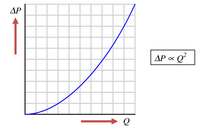
The relationship between flow rate and differential pressure for any fluid-accelerating flow element is non-linear. When plotted on a graph, the relationship between flow rate (Q) and differential pressure (∆P) is quadratic, like one-half of a parabola.
Differential pressure developed by a venturi, orifice plate, pitot tube, or any other acceleration-based flow element is proportional to the square of the flow rate:

The traditional means of implementing the necessary signal characterization was to install a “square root” function relay between the transmitter and the flow indicator, as shown in the following diagram:
In the days of pneumatic instrumentation, this square-root function was performed in a separate device called a square root extractor.
The Foxboro model 557 (2) and Moore Products Model 65 (1) pneumatic square root extractors are classic examples of this technology :
Pneumatic square root extraction relays provide a square-root function that the relays were able to serve their purpose in characterizing the output flow signal of a pressure sensor to yield a signal representing flow rate.
The following table shows the ideal response of a pneumatic square root relay:
As you can see from the table, the square-root relationship is most evident in comparing the input and output percentage values.
For example, at an input signal pressure of 6 PSI (25%), the output signal percentage will be the square root of 25%, which is 50% (0.5 = √0.25) or 9 PSI as a pneumatic signal.
At an input signal pressure of 10 PSI (58.33%), the output signal percentage will be 76.38%, because of 0.7638 = √0.5833, yielding an output signal pressure of 12.17 PSI.
When graphed, the function of a square-root extractor is precisely opposite (inverted) of the quadratic function of a flow-sensing element such as an orifice plate, venturi, or pitot tube:
When we connect the output of the DP transmitter to the input of Square Root Extractor, the square-root function applies to the output signal – the result is an output signal that tracks linearly with flow rate (Q).
An instrument connected to the square root relay’s signal will, therefore, register the flow rate as it should.
Note: We are not using the square-root extractor devices anymore, these are replaced with modern DP Transmitters.
The modern solution to this problem is to incorporate square-root signal characterization either inside the transmitter or inside the receiving instrument (e.g. indicator, recorder, or controller).
Either way, the square-root function must be implemented somewhere in the loop in order that flow may be accurately measured throughout the operating range.
Read: Square-root in DCS or Transmitter?
Author: Tony R. Kuphaldt
If you liked this article, then please subscribe to our YouTube Channel for Instrumentation, Electrical, PLC, and SCADA video tutorials.
You can also follow us on Facebook and Twitter to receive daily updates.
Read Next:
Lube oil consoles of rotary equipment packages in industrial process plants are usually equipped with…
Rotating equipment packages such as pumps, compressors, turbines need the lube oil consoles for their…
This article explains how to blink lights in ladder logic with a detailed explanation video…
In this article, a simple example will teach you the conversion from Boolean algebra to…
In this article, you will learn the PLC cooking timer example for kitchen automation using…
Learn an example PLC program to control a pump based on level sensors using ladder…