Inst ToolsInst ToolsInst Tools
  • Courses
  • Automation
    • PLC
    • Control System
    • Safety System
    • Communication
    • Fire & Gas System
  • Instrumentation
    • Design
    • Pressure
    • Temperature
    • Flow
    • Level
    • Vibration
    • Analyzer
    • Control Valve
    • Switch
    • Calibration
    • Erection & Commissioning
  • Interview
    • Instrumentation
    • Electrical
    • Electronics
    • Practical
  • Q&A
    • Instrumentation
    • Control System
    • Electrical
    • Electronics
    • Analog Electronics
    • Digital Electronics
    • Power Electronics
    • Microprocessor
  • Request
Search
  • Books
  • Software
  • Projects
  • Process
  • Tools
  • Basics
  • Formula
  • Power Plant
  • Root Cause Analysis
  • Electrical Basics
  • Animation
  • Standards
  • 4-20 mA Course
  • Siemens PLC Course
Reading: What is Smart or Intelligent MCC?
Share
Font ResizerAa
Inst ToolsInst Tools
Font ResizerAa
  • Courses
  • Design
  • PLC
  • Interview
  • Control System
Search
  • Courses
  • Automation
    • PLC
    • Control System
    • Safety System
    • Communication
    • Fire & Gas System
  • Instrumentation
    • Design
    • Pressure
    • Temperature
    • Flow
    • Level
    • Vibration
    • Analyzer
    • Control Valve
    • Switch
    • Calibration
    • Erection & Commissioning
  • Interview
    • Instrumentation
    • Electrical
    • Electronics
    • Practical
  • Q&A
    • Instrumentation
    • Control System
    • Electrical
    • Electronics
    • Analog Electronics
    • Digital Electronics
    • Power Electronics
    • Microprocessor
  • Request
Follow US
All rights reserved. Reproduction in whole or in part without written permission is prohibited.
Inst Tools > Blog > Electrical Basics > What is Smart or Intelligent MCC?

What is Smart or Intelligent MCC?

A Smart MCC uses intelligent devices with dedicated controller with profibus communication to monitor & control the motors.

Last updated: March 20, 2021 7:16 pm
Editorial Staff
Electrical Basics
No Comments
Share
5 Min Read
SHARE

What is MCC?

MCC is acronyms for motor control center. MCC contains all the switchgears like switch fuse unit, power contactor, auxiliary contactor, overload relay, ampere meter, voltmeter, energy meter and miscellaneous items to control and monitor the operation of the motor.

Contents
What is MCC?What is Smart or Intelligent MCC?Advantages of Smart or Intelligent MCC

The conventional MCC has metering class current transformer mounted for each phase to monitor the motor current and energy drawn by the motor. The protection class current transformer is mounted and wired with thermal or electronic overload relay to isolate the supply in the event of overload or fault in the motor.

The MCC has a lot of wirings to incorporate all switchgears, meters and protection relays. The fault history is not available in conventional MCC.

Moreover, troubleshooting is more complex and preventive maintenance schedule is difficult to fix because the feeder fault and maintenance history are not available.

After advancement in the automation, the conventional MCC is now upgraded to the intelligent or smart MCC.

What is Smart or Intelligent MCC?

A Smart MCC uses intelligent devices with dedicated controller with profibus communication to monitor & control the motors or other electrical loads.

For Example: In smart MCC, all motor feeders are configured with the required configurations like maximum current, maximum voltage, trips, faults, alarms, etc. All the feeders are configured with a unique slave address (ID) and placed in one or more profibus networks. We can connect upto 126 devices in a network. The real-time motor parameters will be monitored in stand-alone SCADA system or the same data can be transferred to control room PLC or DCS systems.

We can connect and communicate different types of devices in a profibus network like feeders, soft-starters, VFD’s, or any device which supports profibus communication.

Image courtesy: Siemens

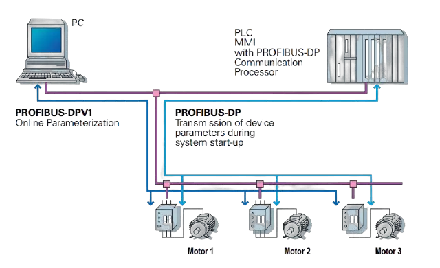
A smart device incorporates intelligent devices like current module, voltage module and it’s controller in the MCC which takes the motor operating data and communicate the same to PLC or process control system.

The motor protections like overload, overcurrent, instantaneous over current, locked rotor fault and phase failure is immediately reported to PLC connected to the MCC intelligent device. Thus, the protection is very fast and reliable.

 Further, all the motor protection parameters can be programmed remotely from the PLC. The energy, current, voltage, power and running hours is recorded in the computer.

The running hours recorded data can be used for preventive maintenance of the motor.

Smart or Intelligent MCC
Image courtesy: Siemens

Advantages of Smart or Intelligent MCC

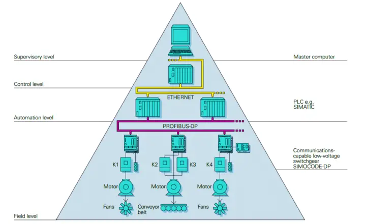
  • All the intelligent devices of feeders are connected in loop on profibus-DP communication. Thus all the intelligent devices connected to the profibus network and transfers the data quickly to PLC. The speed of data is very fast with intelligent MCC.
  • The wiring from PLC to MCC is greatly reduced. All the analog and digital signal is communicated on the same communication bus and thus, there is no need of additional I/O modules and their wiring.
  • The motor monitoring and protection parameters can be programmed from PLC/SCADA through remote programming station with respective software.
  • The size of the MCC reduces because of less wiring and no need of protection relay and phase failure relay.
  • The motor maintenance is done after certain hours running. The data of motor running hours is available in PLC. The output report from PLC can be generated for maintenance purpose.
  • Reduces motor failure rate because the motor gets tripped quickly with overload faults.

Author: Satyadeo Vyas

If you liked this article, then please subscribe to our YouTube Channel for Instrumentation, Electrical, PLC, and SCADA video tutorials.

You can also follow us on Facebook and Twitter to receive daily updates.

Read Next:

  • What is a Fieldbus?
  • Electric Fence Gates
  • Electrical Single Line Diagram
  • What is a Protective Relay?
  • Torque Boosting in Variable Frequency Drive
Don't Miss Our Updates
Be the first to get exclusive content straight to your email.
We promise not to spam you. You can unsubscribe at any time.
Invalid email address
You've successfully subscribed !

Continue Reading

Induction Motor Over and Under Voltage Problems
Types of Circuit Breakers, Advantages, Disadvantages
Difference Between Power Cable and Instrument Cable
Types of MCB
What Happens When a Pump Runs Dry? How to Avoid it?
Difference Between NEMA and IEC Motors?
Share This Article
Facebook Whatsapp Whatsapp LinkedIn Copy Link
Share
Leave a Comment

Leave a Reply Cancel reply

Your email address will not be published. Required fields are marked *

Stay Connected

128.3kFollowersLike
69.1kFollowersFollow
210kSubscribersSubscribe
38kFollowersFollow

Categories

Explore More

Basic Electrical Engineering Questions & Answers
Emergency Stop Switch Spurious Trip
How to Test a Motor using Megger?
Control Two Motors in Sequence after Time Delay – Circuit, Operation
Motor Control Timer Circuit – Automatic Motor START and STOP
Difference Between Normal Inverter and Solar Inverter
Motor Maintenance, Troubles, Regular Checks, Performance
What is a Time Delay Fuse? – Principles and Advantages

Keep Learning

Earth Fault

What are Ground Fault and Earth Fault?

Gas-Insulated Transmission Line

What is Gas-Insulated Transmission Line? Principle Advantages

Difference between Current Transformer and Potential Transformer

Difference between Current Transformer and Potential Transformer

Pros and Cons of Soft Starter

Pros and Cons of Soft Starter

Bonding and Grounding Electrical Systems

Testing and Inspection of Bonding and Grounding Systems

Difference between Servo Motor and DC Motor

Difference between Servo Motor and DC Motor

Fence grounding specifications

All About Electric Fence Gates

Why is Motor Control Required in Control Systems

Why is Motor Control Required in Control Systems?

Learn More

Thermocouples

Important Factors for Thermocouple Selection

Comparison of CB, CE & CC Amplifiers

Comparison of Transistor Configurations

radial-vane damper

Dampers and Louvres

Pressure Transmitter Calibration Procedure

Pressure Transmitter Calibration Procedure

ICS System Design

ICS System Design Considerations

MOSFET VI Characteristics

Power MOSFET

Steam Turbine Driven Centrifugal Compressors Leak due to Broken Instrument

Steam Turbine Driven Centrifugal Compressors Leak due to Broken Instrument

ORP-sensor-calibration

Oxidation-Reduction Potential (ORP) Sensor Calibration Procedure

Menu

  • About
  • Privacy Policy
  • Copyright

Quick Links

  • Learn PLC
  • Helping Hand
  • Part Time Job

YouTube Subscribe

Follow US
All rights reserved. Reproduction in whole or in part without written permission is prohibited.
Welcome Back!

Sign in to your account

Username or Email Address
Password

Lost your password?