Inst ToolsInst ToolsInst Tools
  • Courses
  • Automation
    • PLC
    • Control System
    • Safety System
    • Communication
    • Fire & Gas System
  • Instrumentation
    • Design
    • Pressure
    • Temperature
    • Flow
    • Level
    • Vibration
    • Analyzer
    • Control Valve
    • Switch
    • Calibration
    • Erection & Commissioning
  • Interview
    • Instrumentation
    • Electrical
    • Electronics
    • Practical
  • Q&A
    • Instrumentation
    • Control System
    • Electrical
    • Electronics
    • Analog Electronics
    • Digital Electronics
    • Power Electronics
    • Microprocessor
  • Request
Search
  • Books
  • Software
  • Projects
  • Process
  • Tools
  • Basics
  • Formula
  • Power Plant
  • Root Cause Analysis
  • Electrical Basics
  • Animation
  • Standards
  • 4-20 mA Course
  • Siemens PLC Course
Reading: What is a Inductive Proximity Switch ?
Share
Font ResizerAa
Inst ToolsInst Tools
Font ResizerAa
  • Courses
  • Design
  • PLC
  • Interview
  • Control System
Search
  • Courses
  • Automation
    • PLC
    • Control System
    • Safety System
    • Communication
    • Fire & Gas System
  • Instrumentation
    • Design
    • Pressure
    • Temperature
    • Flow
    • Level
    • Vibration
    • Analyzer
    • Control Valve
    • Switch
    • Calibration
    • Erection & Commissioning
  • Interview
    • Instrumentation
    • Electrical
    • Electronics
    • Practical
  • Q&A
    • Instrumentation
    • Control System
    • Electrical
    • Electronics
    • Analog Electronics
    • Digital Electronics
    • Power Electronics
    • Microprocessor
  • Request
Follow US
All rights reserved. Reproduction in whole or in part without written permission is prohibited.
Inst Tools > Blog > Switches > What is a Inductive Proximity Switch ?

What is a Inductive Proximity Switch ?

Inductive Proximity Switches respond to targets that come within the active range of their generated sensing fields. Proximity Switch Working Principle.

Last updated: March 27, 2023 12:39 pm
Editorial Staff
Switches
No Comments
Share
2 Min Read
SHARE

Inductive Proximity Switch is a device which causes a switching action without physical contact. Inductive Proximity Switches respond to targets that come within the active range of their generated sensing fields. These units are completely self-contained, and house a field generator, amplifier, and other necessary circuitry to accomplish electronic switching.

The devices are all solid state and have no moving parts that can wear out. The electronic switches are not susceptible to contact contamination, contact erosion, or material transfer as are mechanical switches.

The switching is insensitive to vibration, and is positive without chatter, regardless of how slowly the target approaches or recedes from the sensor.

What is a Inductive Proximity Switch

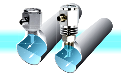
The oscillator resonant circuit, located in the proximity switch, uses an open core coil to help produce a concentrated high frequency electro-magnetic field, which emerges from the active surface of the sensor.

If a metal target enters this field, eddy currents are induced.

Inductive Proximity Switch Working Principle

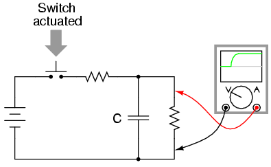
The floating induced eddy current draws energy from the LC circuit. The load on the oscillator circuit evokes a decrease in the oscillating amplitude. The oscillator is attenuated. The decrease of the oscillating amplitude is converted into an electrical signal by the electronic circuit, which leads to a change of switching state of the proximity switch.

When the electric conductive material is removed from the inductive field, the pulse amplitude increases and via the electronic circuit the original switching position is recreated. The oscillator is unattenuated.

Proximity Switch Function

The inductive proximity switch is based upon the principle of an attenuated LC-oscillator. The oscillator circuit coil generates a high frequency magnetic field. This scattering field radiates from the proximity switch sensing face.

If this field is penetrated by ferrous or non-ferrous metals , energy is reduced and thereby the oscillator will be attenuated. The result of changing current consumption is evaluated.

Don't Miss Our Updates
Be the first to get exclusive content straight to your email.
We promise not to spam you. You can unsubscribe at any time.
Invalid email address
You've successfully subscribed !

Continue Reading

How to Calibrate Temperature Switch? – Instrument Basics
Paddle Wheel Level Switch Principle
Optical Level Switch Working Principle
Differential Pressure Switch Working Principle
Pull Up and Pull Down Switch Circuits
Switch Types and Common Terminology
Share This Article
Facebook Whatsapp Whatsapp LinkedIn Copy Link
Share
Leave a Comment

Leave a Reply Cancel reply

Your email address will not be published. Required fields are marked *

Stay Connected

128.3kFollowersLike
69.1kFollowersFollow
210kSubscribersSubscribe
38kFollowersFollow

Categories

Explore More

PLC Example with Switches
In-Line Flow Switch Working Principle and Animation
Float Level Switch Working Principle
Safety Switches for Controlling Conveyor Operations
Limit Switch Animation
Hall Effect Sensor Working Principle Animation
Paddle Switch Working Principle
Differential Pressure Switch Principle

Keep Learning

Limit Switch Schematic

Basics of Limit switches

Electromagnetic limit switch

Electromagnetic and Conductive limit switches Principle

Switch Contact checking with oscilloscope

What is Contact bounce ?

Thermal Dispersion Flow Switch Working Principle

Thermal Dispersion Flow Switch Working Principle

RF-Capacitance Level Switch Principle

RF Capacitance Level Switch Working Principle

Zero Speed Switch Working Principle

Zero Speed Switch Working Principle

Side Mounting Float Switch Working Principle

Side Mounting Float Switch Working Principle

Tuning Fork Level Switch principle

Tuning Fork Level Switch Principle

Learn More

SMART Transmitter

What is a SMART Transmitter?

Submersible Pump

What is a Submersible Pump? Principle Advantages Disadvantages

Data Instance in PLC

Tia Portal – Different Instances of Calling a Function Block

Ammeter with Shunt

Ammeter

Ultrasonic Tank Gauging

Ultrasonic Tank Gauging

Reverse Bias Diode Working Animation

Forward Bias & Reverse Bias Diode Working Animation

Pressure Reducing and Desuperheating Station (PRDS)

Pressure Reducing and DeSuperheating Station (PRDS)

Design Logic Diagrams with Standard Formats for Process Control

Design Logic Diagrams with Standard Formats for Process Control

Menu

  • About
  • Privacy Policy
  • Copyright

Quick Links

  • Learn PLC
  • Helping Hand
  • Part Time Job

YouTube Subscribe

Follow US
All rights reserved. Reproduction in whole or in part without written permission is prohibited.
Welcome Back!

Sign in to your account

Username or Email Address
Password

Lost your password?