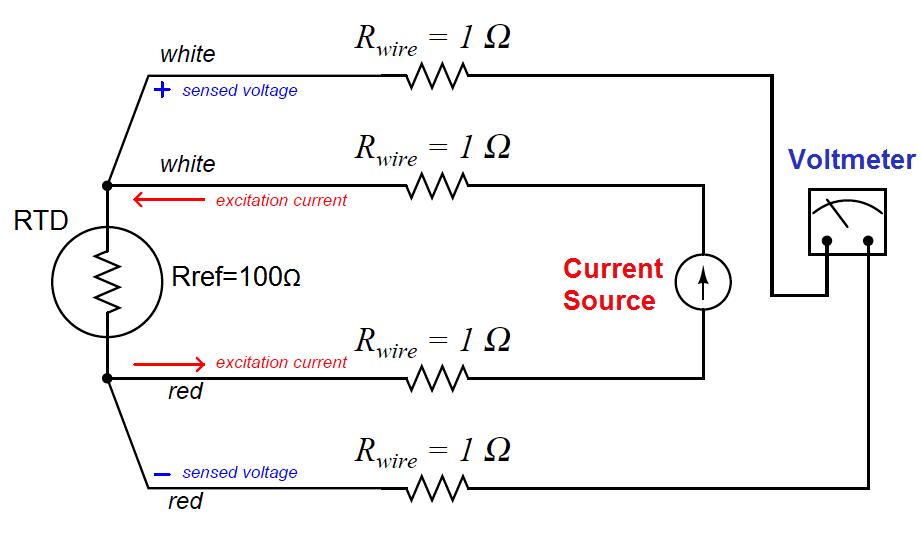
A very old electrical measurement technique known as the Kelvin or four-wire method is a practical solution to the problem of wire resistance.
Commonly employed to make precise resistance measurements for scientific experiments in laboratory conditions, the four-wire technique uses four wires to connect the resistance under test (in this case, the RTD) to the measuring instrument, which consists of a voltmeter and a precision current source.
Two wires carry “excitation” current to the RTD from the current source while the other two wires merely “sense” voltage drop across the RTD resistor element and carry that voltage signal to the voltmeter.
RTD resistance is calculated using Ohm’s Law: taking the measured voltage displayed by the voltmeter and dividing that figure by the regulated current value of the current source.
A simple 4-wire RTD circuit is shown here for illustration:

Wire resistances are completely inconsequential in this circuit. The two “excitation” wires carrying current to the RTD will drop some voltage along their length, but this voltage drop is only “seen” by the current source and not the voltmeter.
The two “sense” wires connecting the voltmeter to the RTD also possess resistance, but they drop negligible voltage because the voltmeter draws so little current through them.
Thus, the resistances of the current-carrying wires are of no effect because the voltmeter never senses their voltage drops, and the resistances of the voltmeter’s sensing wires are of no effect because they carry practically zero current.
Note how wire colors (white and red) indicate which wires are common pairs at the RTD. The RTD is polarity-insensitive because it is nothing more than a resistor, which is why it doesn’t matter which color is positive and which color is negative.
The only disadvantage of the four-wire method is the sheer number of wires necessary. Four wires per RTD can add up to a sizeable wire count when many different RTDs are installed in a process area.
Also Read : RTD Standards
Credits : Tony R. Kuphaldt – Creative Commons Attribution 4.0 License
The conveyor sorting machine is widely used in the packing industries using the PLC program…
Learn the example of flip-flop PLC program for lamps application using the ladder logic to…
In this article, you will learn the STAR DELTA programming using PLC controller to start…
Lube oil consoles of rotary equipment packages in industrial process plants are usually equipped with…
Rotating equipment packages such as pumps, compressors, turbines need the lube oil consoles for their…
This article explains how to blink lights in ladder logic with a detailed explanation video…
View Comments
Sir, a pressure transmitter of Honeywell shows error Pu comm failed. Sir I can't understand what is the problem?