Inst ToolsInst ToolsInst Tools
  • Courses
  • Automation
    • PLC
    • Control System
    • Safety System
    • Communication
    • Fire & Gas System
  • Instrumentation
    • Design
    • Pressure
    • Temperature
    • Flow
    • Level
    • Vibration
    • Analyzer
    • Control Valve
    • Switch
    • Calibration
    • Erection & Commissioning
  • Interview
    • Instrumentation
    • Electrical
    • Electronics
    • Practical
  • Q&A
    • Instrumentation
    • Control System
    • Electrical
    • Electronics
    • Analog Electronics
    • Digital Electronics
    • Power Electronics
    • Microprocessor
  • Request
Search
  • Books
  • Software
  • Projects
  • Process
  • Tools
  • Basics
  • Formula
  • Power Plant
  • Root Cause Analysis
  • Electrical Basics
  • Animation
  • Standards
  • 4-20 mA Course
  • Siemens PLC Course
Reading: What is a Filter Circuit ?
Share
Font ResizerAa
Inst ToolsInst Tools
Font ResizerAa
  • Courses
  • Design
  • PLC
  • Interview
  • Control System
Search
  • Courses
  • Automation
    • PLC
    • Control System
    • Safety System
    • Communication
    • Fire & Gas System
  • Instrumentation
    • Design
    • Pressure
    • Temperature
    • Flow
    • Level
    • Vibration
    • Analyzer
    • Control Valve
    • Switch
    • Calibration
    • Erection & Commissioning
  • Interview
    • Instrumentation
    • Electrical
    • Electronics
    • Practical
  • Q&A
    • Instrumentation
    • Control System
    • Electrical
    • Electronics
    • Analog Electronics
    • Digital Electronics
    • Power Electronics
    • Microprocessor
  • Request
Follow US
All rights reserved. Reproduction in whole or in part without written permission is prohibited.
Inst Tools > Blog > Electronic Devices & Circuits > What is a Filter Circuit ?

What is a Filter Circuit ?

Last updated: September 27, 2016 3:56 pm
Editorial Staff
Electronic Devices & Circuits
No Comments
Share
2 Min Read
SHARE

Generally, a rectifier is required to produce pure d.c. supply for using at various places in the electronic circuits. However, the output of a rectifier has pulsating character i.e. it contains a.c. and d.c. components. The a.c. component is undesirable and must be kept away from the load.  To do so, a filter circuit is used which removes (or filters out) the a.c. component and allows only the d.c. component to reach the load.

A filter circuit is a device which removes the a.c. component of rectifier output but allows the d.c. component to reach the load.

What is a Filter Circuit

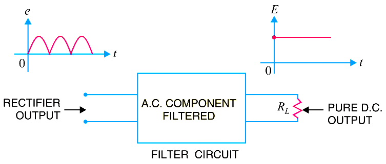
Obviously, a filter circuit should be installed between the rectifier and the load as shown in Fig. A filter circuit is generally a combination of inductors (L) and capacitors (C). The filtering action of L and C depends upon the basic electrical principles.  A capacitor passes a.c. readily but does not pass d.c. at all.

On the other hand, an inductor opposes a.c. but allows d.c. to pass through it.  It then becomes clear that suitable network of L and C can effectively remove the a.c. component, allowing the d.c. component to reach the load.

Types of Filter Circuits

The most commonly used filter circuits are

  1. capacitor filter,
  2. choke input filter and
  3. capacitor input filter or π-filter.
Don't Miss Our Updates
Be the first to get exclusive content straight to your email.
We promise not to spam you. You can unsubscribe at any time.
Invalid email address
You've successfully subscribed !

Continue Reading

CRT Fluorescent Screen
Transistor Biasing
Summary Of Transistor Bias Circuits
Optoisolator Working Principle
Time Base Generator
pi filter Operation
Share This Article
Facebook Whatsapp Whatsapp LinkedIn Copy Link
Share
Leave a Comment

Leave a Reply Cancel reply

Your email address will not be published. Required fields are marked *

Stay Connected

128.3kFollowersLike
69.1kFollowersFollow
210kSubscribersSubscribe
38kFollowersFollow

Categories

Explore More

Different Types of Diodes
Bipolar Junction Transistor Construction
Zener Diode Voltage Regulator Operation
Current Divider Rule
Phototransistor Working Principle
Photodiode as Variable Resistance Device
Operation of Zener Diode Voltage Regulator
Power MOSFET Safe Operating Area

Keep Learning

p-type-semiconductor

N Type and P Type Semiconductors

Testing a defective transistor

Testing a Transistor with a Digital Multimeter

Combining Independent Current Sources in Parallel

Combining Independent Current Sources in Parallel

example-of-KCL

What is Kirchhoff’s Current Law

Voltage Divider Rule

Voltage Divider Rule

Reverse Voltage Characteristics of Photo diode

Characteristics of Photo diode

Diode-testing-with-multimeter

How to Test a Diode using Multimeter

Zener Diode

Zener Diode Breakdown Characteristics

Learn More

Fieldbus and Profibus

Difference between Fieldbus and Profibus

Valve Basics

Basics of Control Valves

Surface Detector Level Measurement System

Surface Detector Level Gauges (Plumb-bob)

Mechanical Engineering Design and Fabrication Projects

300+ Mechanical Engineering Design and Fabrication Projects

Digital Electronics Multiple Choice Questions

Master-Slave Flip-Flops Objective Questions

Baffle Nozzle Assembly Sensitive Mechanism

Baffle Nozzle Assembly Sensitive Mechanism

FOUNDATION Fieldbus junction boxes

Fieldbus Cables

Two Transistor Model of Thyristor

Thyristors – Switching, Two Transistor Model, Advantage, Applications

Menu

  • About
  • Privacy Policy
  • Copyright

Quick Links

  • Learn PLC
  • Helping Hand
  • Part Time Job

YouTube Subscribe

Follow US
All rights reserved. Reproduction in whole or in part without written permission is prohibited.
Welcome Back!

Sign in to your account

Username or Email Address
Password

Lost your password?