Learn how to create a waste-burning system with a weighing function example with the CX-Programmer OMRON PLC program using the Counter, Timer, and KEEP instructions.
Waste-Burning System
This PLC program has 4 buttons, the START_SYSTEM (0.00) button is used to turn ON the system, the STOP_SYSTEM (0.01) button is used to turn OFF the system, the FINISH_BUTTON (0.02) button is used to turn OFF the Finish Alarm, the RESET _COUNTER (0.03) button is used to Reset data in memory word COUNTER_SYSTEM(D0).
In this PLC program, when the START_SYSTEM (0.00) button is pressed, the system will be in a Standby state.
When the Weighing Indicator detects that the collected waste has exceeded the “Set value/25kg” limit, the burning process will be carried out and the Output BURNING_SYSTEM (100.00) will be ON.
The burning process will be carried out for 15 seconds and continued with the cooling process.
The cooling process will be carried out for 10 seconds and the EXHAUST_FAN (100.01) Output will be ON.
When the cooling process is complete, the ALARM_FINISH (100.02) output becomes ON. This alarm indicates that the waste burning and cooling process has been completed.
The ALARM_FINISH (100.02) Output will be OFF if the FINISH_BUTTON (0.02) button is Pressed.
The memory word COUNTER_SYSTEM (D10) will count the processes that have been carried out.
The memory word COUNTER_SYSTEM (D10) will be Reset to zero “0” if the RESET _COUNTER (0.03) button is Pressed.
When the STOP_SYSTEM (0.01) button is pressed, the system will be OFF.
Program IO Details
| Comment | Input (I) | Output (Q) | Memory Bits | Memory Words | Timers |
| START_SYSTEM | 0.00 | ||||
| STOP_SYSTEM | 0.01 | ||||
| FINISH_BUTTON | 0.02 | ||||
| RESET_COUNTER | 0.03 | ||||
| BURNING_SYSTEM | 100.00 | ||||
| EXHAUST_FAN | 100.01 | ||||
| ALARM_FINISH | 100.02 | ||||
| BURNING_TIMER | T0000 | ||||
| COOLING_TIMER | T0001 | ||||
| SYSTEM_ON | W0.00 | ||||
| WEIGHING_INDICATOR | D0 | ||||
| COUNTER_SYSTEM | D10 |
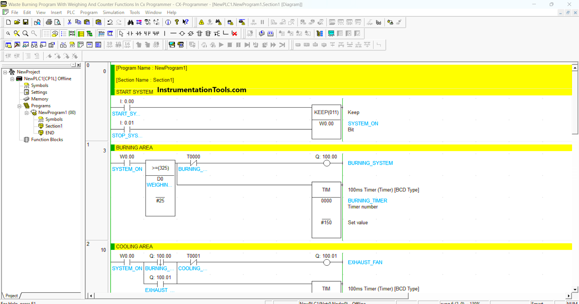
OMRON PLC Program Example
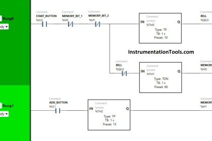
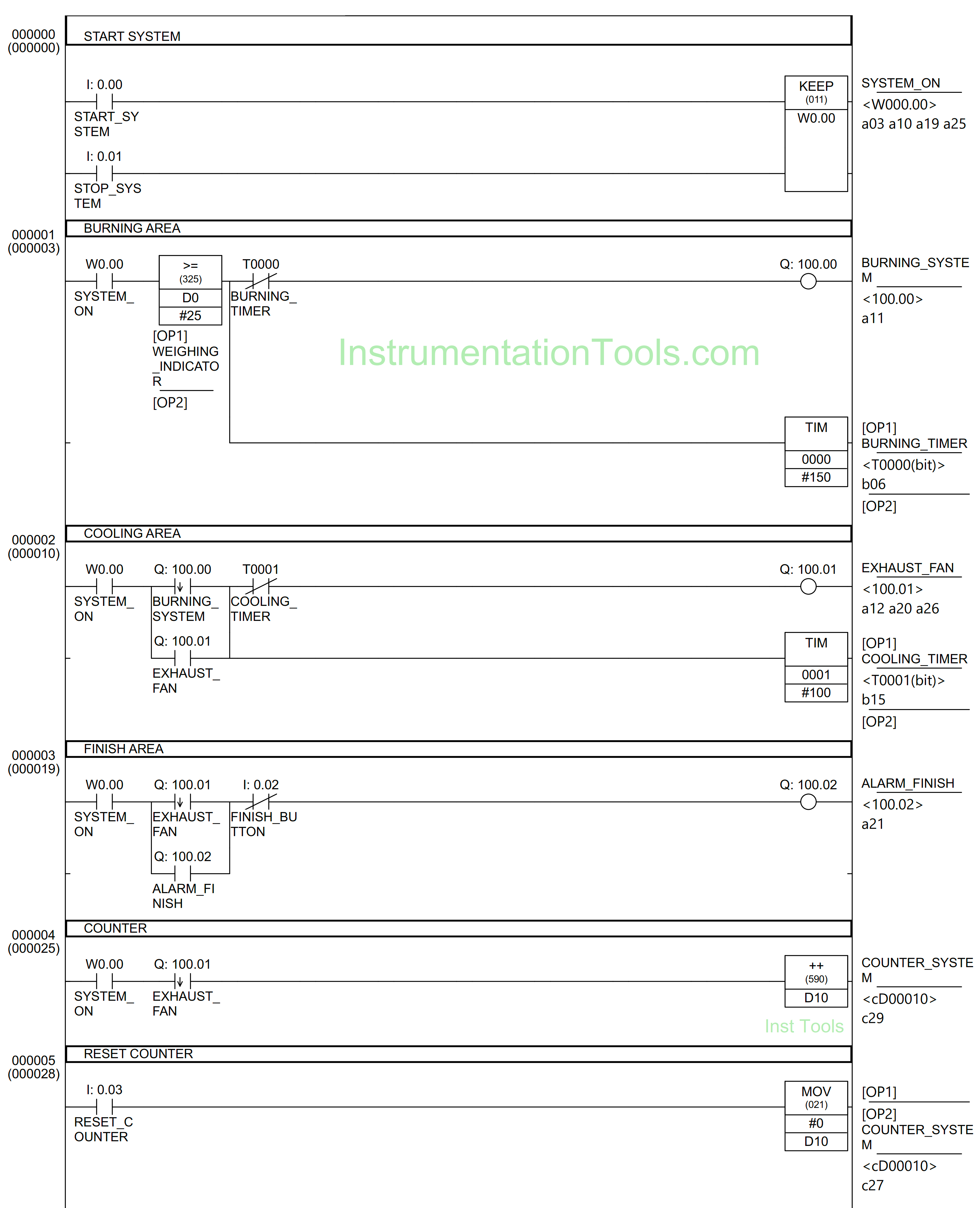
RUNG 0 (SYSTEM_ON)
In this Rung, when the START_SYSTEM (0.00) button is pressed, the memory bit SYSTEM_ON( W0.00) will be in the HIGH state. Because it uses the KEEP (011) instruction, the memory bit SYSTEM_ON(W0.00) remains in the HIGH state even though START_SYSTEM (0.00) button has been Released.
The memory bit SYSTEM_ON (W0.00) will change to LOW state if the STOP_SYSTEM (0.01) button is Pressed.
RUNG 1 (BURNING AREA)
In this Rung, when the NO contact of memory bit SYSTEM_ON (W0.00) in HIGH state and the memory word WEIGHING_INDICATOR (D0) has a value Greater Than Or Equal to “25”, then the BURNING_SYSTEM (100.00) Output will be ON and the timer BURNING_TIMER (T0000) Start counting up to 15 seconds.
The BURNING_SYSTEM (100.00) Output will be OFF when the BURNING_TIMER (T0000) timer has finished counting. When the memory word WEIGHING_INDICATOR (D0) is Less Than Or Not Equal to “25”, then the BURNING_TIMER (T0000) timer will be Reset.
RUNG 2 (COOLING AREA)
In this Rung, when the NO contact of memory bit SYSTEM_ON (W0.00) in HIGH state and the NO contact of BURNING_SYSTEM (100.00) Output is ON, the EXHAUST_FAN (100.01) Output will be ON and the timer COOLING_TIMER (T0001) Starts counting up to 10 seconds.
Because it uses Latching, the EXHAUST_FAN (100.01) Output remains ON even though the BURNING_SYSTEM (100.00) Output is OFF. The EXHAUST_FAN (100.01) Output will be OFF when the timer COOLING_TIMER (T0001) has finished counting.
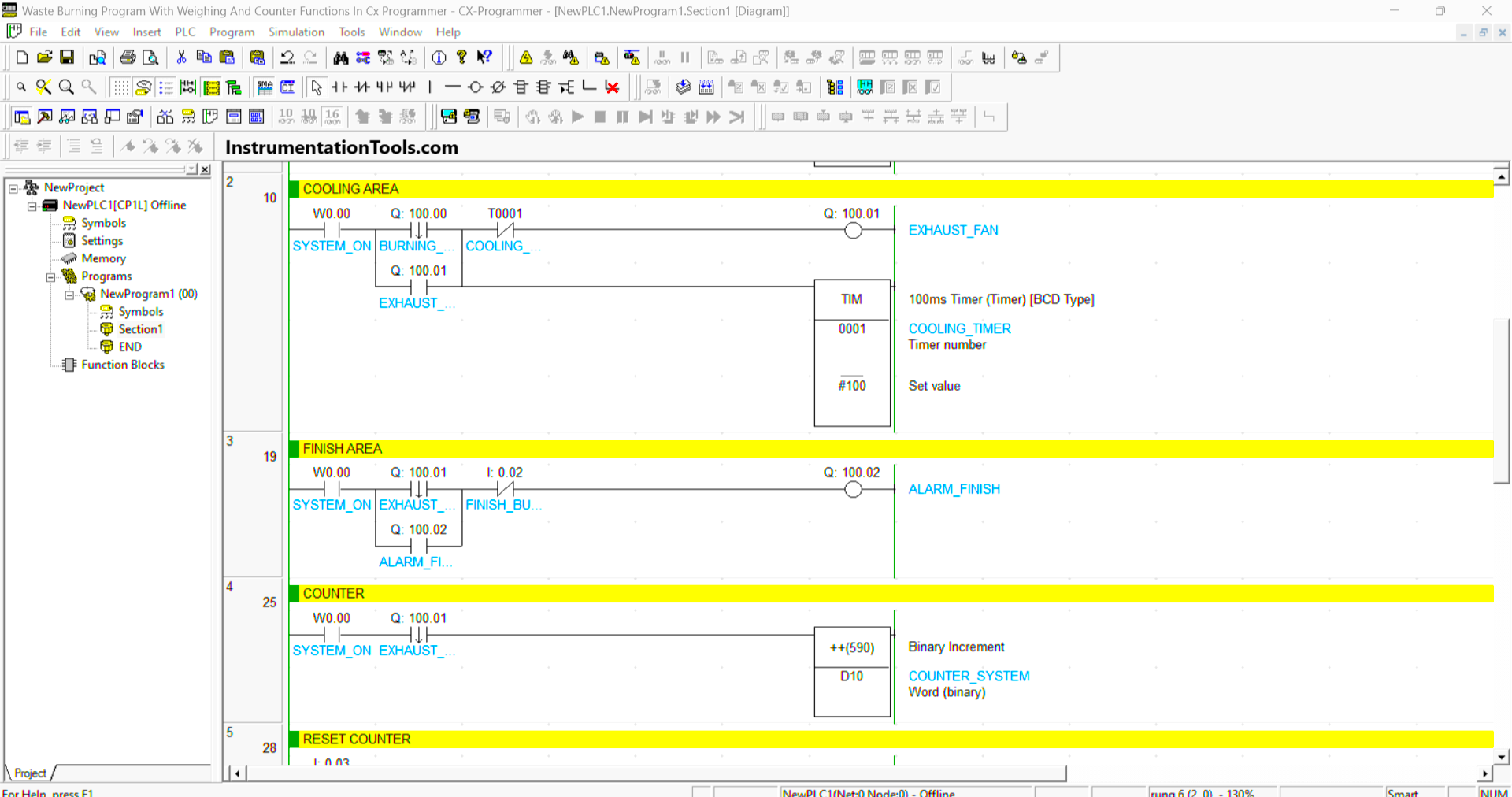
RUNG 3 (FINISH AREA)
In this Rung, when the NO contact of memory bit SYSTEM_ON (W0.00) is in a HIGH state and the NO contact of EXHAUST_FAN (100.01) Output is ON, then the ALARM_FINISH (100.02) Output will be ON.
Because it uses Latching, the ALARM_FINISH (100.02) Output remains ON even though the EXHAUST_FAN (100.01) Output is OFF. The ALARM_FINISH (100.02) Output will be OFF if the FINISH_BUTTON (0.02) button is Pressed.
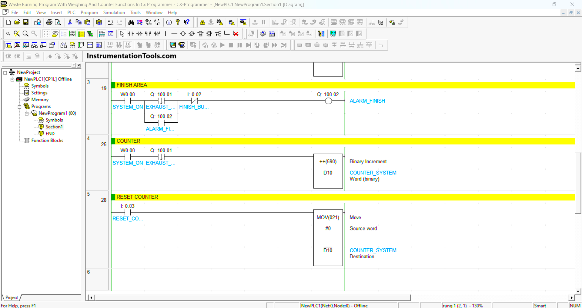
RUNG 4 (COUNTER)
When the NO contact of memory bit SYSTEM_ON (W0.00) in HIGH state and the NO contact of EXHAUST_FAN (100.01) Output is ON, then the value in memory word COUNTER_SYSTEM (D10) will increase (+1).
RUNG 5 (RESET COUNTER)
In this rung, if the RESET_COUNTER (0.03) button is pressed, the data in memory word COUNTER_SYSTEM (D10) will be Reset to zero “0”.
Read Next:
- PLC Product Sticker Machine with Weighing
- Automatic Exhaust Fan XG5000 PLC Program
- Perfume Mixing and Filling System PLC Logic
- Product Painting with Omron PLC Program
- Attendance System Program in Omron PLC