A simple DC voltmeter can be constructed by placing a resistor (RS), called a multiplier, in series with the ammeter meter movement, and marking the meter face to read voltage (as shown in Figure).
Voltmeters are connected in parallel with the load (RL) being measured.
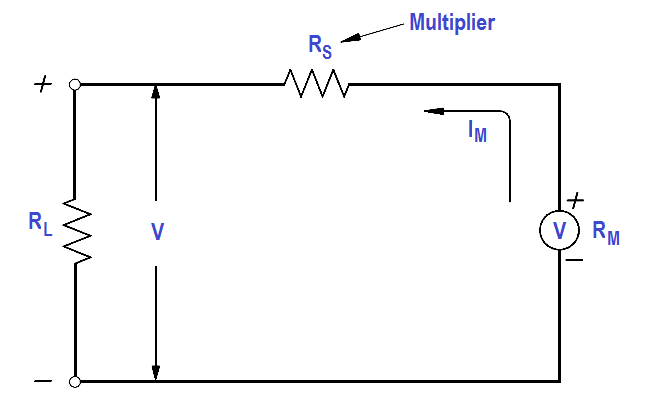
Figure : Simple DC Voltmeter
When constructing a voltmeter, the resistance of the multiplier must be determined to measure the desired voltage. The Equation is a mathematical representation of the voltmeter’s multiplier resistance.
where
V = voltage range desired
Im = meter current
Rm = meter resistance
Rs = multiplier resistance or series resistance
Example:
A 2 mA meter movement with internal resistance of 25 ohms is to be constructed as a voltmeter. What value must the series resistance be to measure full scale voltage of 100 volts?
Solution :
Since Rm is negligibly low, then
Rs = V/Im
Rs = 100 / (2×10⁻³)
Rs = 50kΩ
When a voltmeter is connected in a circuit, the voltmeter will draw current from that circuit. This current causes a voltage drop across the resistance of the meter, which is subtracted from the voltage being measured by the meter. This reduction in voltage is known as the loading effect and can have a serious effect on measurement accuracy, especially for low current circuits.
The accuracy of a voltmeter (Kv ) is defined as the ratio of measured voltage when the meter is in the circuit (Vw) to the voltage measured with the meter out of the circuit.
The below Equation is a mathematical representation of the accuracy of a voltmeter, or true voltage (Vo).
Meter accuracy can also be determined by comparing the relationship between the input and circuit resistances using Ohm’s Law as described below.
where
Im = meter current
Vo = true voltage
Ro = circuit resistance
Rin = input resistance of the voltmeter
Vw = indicated voltage
Kv = meter accuracy
Example:
A voltmeter in the 100 volt range with a sensitivity of 40 KΩ/V is to measure the voltage across terminals ab.
Find :
Solution :
Find Vo , true voltage
Vo = { 100 KΩ / (100 KΩ + 100 KΩ) } x 220 volts
Vo = 110 volts
Find Vw , indicated voltage
Ro = (100 x 100) / (100 + 100) = 50KΩ
Rin = S V = 40KΩ x 100 = 4.4 MΩ
Vw = Rin / (Ro + Rin )
Vw = { 4.4MΩ / (50KΩ + 4.4MΩ) } 110 volts
Vw = 108.9 volts
Find Kv , meter accuracy
Kv = Vw / Vo
Kv = 108.9/110
Kv = 0.99 or 99%
Learn an example PLC program to control a pump based on level sensors using ladder…
In the PLC timer application for security camera recording, when motion is detected then camera…
In this example, we will learn batch mixing with PLC ladder logic program using timer…
This PLC example on manufacturing line assembly is an intermediate-level PLC program prepared for the…
In this article, you will learn the PLC programming example with pushbutton and motor control…
This article teaches how to convert Boolean logic to PLC programming ladder logic with the…


