Inst ToolsInst ToolsInst Tools
  • Courses
  • Automation
    • PLC
    • Control System
    • Safety System
    • Communication
    • Fire & Gas System
  • Instrumentation
    • Design
    • Pressure
    • Temperature
    • Flow
    • Level
    • Vibration
    • Analyzer
    • Control Valve
    • Switch
    • Calibration
    • Erection & Commissioning
  • Interview
    • Instrumentation
    • Electrical
    • Electronics
    • Practical
  • Q&A
    • Instrumentation
    • Control System
    • Electrical
    • Electronics
    • Analog Electronics
    • Digital Electronics
    • Power Electronics
    • Microprocessor
  • Request
Search
  • Books
  • Software
  • Projects
  • Process
  • Tools
  • Basics
  • Formula
  • Power Plant
  • Root Cause Analysis
  • Electrical Basics
  • Animation
  • Standards
  • 4-20 mA Course
  • Siemens PLC Course
Reading: How Process Control Loop Works
Share
Font ResizerAa
Inst ToolsInst Tools
Font ResizerAa
  • Courses
  • Design
  • PLC
  • Interview
  • Control System
Search
  • Courses
  • Automation
    • PLC
    • Control System
    • Safety System
    • Communication
    • Fire & Gas System
  • Instrumentation
    • Design
    • Pressure
    • Temperature
    • Flow
    • Level
    • Vibration
    • Analyzer
    • Control Valve
    • Switch
    • Calibration
    • Erection & Commissioning
  • Interview
    • Instrumentation
    • Electrical
    • Electronics
    • Practical
  • Q&A
    • Instrumentation
    • Control System
    • Electrical
    • Electronics
    • Analog Electronics
    • Digital Electronics
    • Power Electronics
    • Microprocessor
  • Request
Follow US
All rights reserved. Reproduction in whole or in part without written permission is prohibited.
Inst Tools > Blog > Control Systems > How Process Control Loop Works

How Process Control Loop Works

Last updated: July 15, 2019 4:18 pm
Editorial Staff
Control Systems
2 Comments
Share
4 Min Read
SHARE

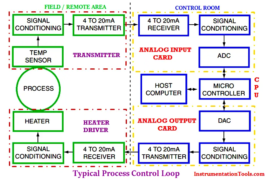
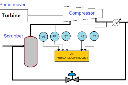
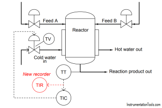
A typical process control system is shown in Figure. Assume the physical variable to be controlled is the temperature.

Basically Industrial process control loop consists of sensors, transmitters, Control systems (PLC/DCS), control valves, Electrical drives etc. These all equipment’s  installed in different areas of plant.

Typical process control loop

The Basic Plant areas classified as follows :

1.Field : Sensors, Transmitters, Control valves, on/off valves, local control panels etc.

2.Control Room : PLC, DCS, Microcontroller based controllers etc.

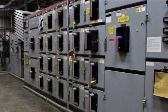
3.Substation : Variable Frequency Drives, Smart Feeders, Softstarters etc.

Basic Process Control Loop Example:

Now we are discussing about a basic temperature process control loop using a heater.

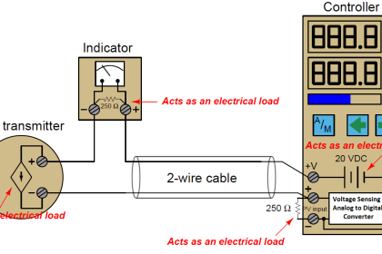
A Temperature Transmitters is required to measure the process variable i.e. process temperature. The transmitters have consists of sensors, signal conditioning circuit and 4-20mA converter. The transmitters basically measures the temperature and provides an output in 4-20mA current which is equivalent to measured temperature.

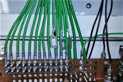
The transmitter output will goes to the PLC/DCS which is installed in control room. The transmitter wiring is terminated in Marshalling cabinet of PLC/DCS and an internal wiring is provided so that this transmitters output will  be routed from marshalling cabinet to system cabinet.

The system cabinet have Analog Input cards, Analog Output cards, Communication cards, CPU etc. As transmitters is an input to the system so it will be connected to Analog input card.

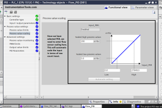
The Analog input card converts the received 4-20mA into equivalent 1-5v DC using a standard 250 ohms resistor. Then an Analog to Digital Converter (ADC) converts this 1-5V DC into equivalent Binary Codes.

The Analog input card output will be connected to the Processor (CPU). The Processor converts this binary codes into operator readable format i.e. say temperature in degrees and it will be displayed in Graphics.

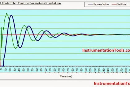
Say, Now the measured temperature value found little bit high when compared to setpoint. If the loop in auto mode then PID controller will takes the necessary action automatically as per predefined program. If the loop in Manual mode then the operator has to take action manually. Note for easy discussion consider loop in auto mode.

Here in our example we have an heater which is controlling the temperature. heater have standard 4-20mA input which is used for controlling the temperature from 0 to 100% of heater range.

As assumed the measured temperature is high so PID controller decides to reduce the temperature.The Analog Output card is connected to the heater, so Processor (CPU) sends a equivalent Binary coded signal to the Analog Output card.

The Analog Output card converts the Binary coded signal using a Digital to Analog converter (DAC) which is recieved from Processor and sends an equivalent 4-20mA signal to the heater. The heater receives the 4-20mA from the PLC then takes the necessary action and finally controls the temperature to the desired value.

The Human Machine Interface (HMI) nothing but a computer used for displaying the graphics to the operator. The graphics receives all the signals from the Processor and displays to the operator.

Notice that the interface between the control room and the substation, remote process area or field is via the industry standard 4–20mA loop.

Don't Miss Our Updates
Be the first to get exclusive content straight to your email.
We promise not to spam you. You can unsubscribe at any time.
Invalid email address
You've successfully subscribed !

Continue Reading

Industrial Automation Pre-Engineering Design Documents – Project & Process
What is Instrument Hook Up Diagram ?
Zener Diode Barrier Principle
Feedforward Vs Feedback Control
4-wire Transmitters Current Loops
Control Modes of Air Handling Unit (AHU) – HVAC Basics
Share This Article
Facebook Whatsapp Whatsapp LinkedIn Copy Link
Share
2 Comments
  • Roc Shieh says:
    August 15, 2016 at 5:07 am

    A good process control loop diagram. I like.

    Reply
  • Babu KR says:
    December 17, 2016 at 5:29 am

    Excellent explanations. Understandable, simple & clear.

    Reply

Leave a Reply Cancel reply

Your email address will not be published. Required fields are marked *

Stay Connected

128.3kFollowersLike
69.1kFollowersFollow
210kSubscribersSubscribe
38kFollowersFollow

Categories

Explore More

How does a Redundant Controller comes in line when the Main Controller fails?
What is the DDE Protocol?
ON-OFF Controller Principle
Instrumentation and Electrical Teams Interactions (Detail Design Engineering)
PID Controllers with Output High Select Logic
How Engineers Effectively do Problem-solve and Troubleshoot?
What is a Feedback Control System? Types & Advantages
Limit, Selector, and Override controls

Keep Learning

Difference Between PNP and NPN Sensors

Difference Between PNP and NPN Sensors

Loop Splitter Theory of Operation

4-20 mA Loop Splitter

Difference between ON-OFF Controller and PID Controller

Difference between ON-OFF Controller and PID Controller

Industry 4.0

Industry 4.0

Instrumentation Design Details

I&C Engineer Roles & Responsibilities – Instrumentation Design

GuideLines for Loop Checks

How to Do Loop Checks During Plant Pre-Commissioning

Cable Glands

Using of MCT instead of Cable Glands on the Cabinets

Two wire loop powered transmitters

4-20 mA Transmitter Wiring Types : 2-Wire, 3-Wire, 4-Wire

Learn More

Solar Pump

What is a Solar Pump VFD? – Advantages, Principle

Transistor Collector Feedback Bias

Transistor Collector Feedback Bias

Input function blocks

FF Function Blocks

water treatment station

What is a Vent Filter? – Water Treatment Plant

Side Mounting Float Switch Working Principle

Side Mounting Float Switch Working Principle

Flow Meters Troubleshooting

Turbine Flow Meters Troubleshooting

Thermocouple Temperature Range

Thermocouple Properties, Temperature Ranges, Element Construction

Electrical Motor Model number and serial number

How to Read the Nameplate of a Motor?

Menu

  • About
  • Privacy Policy
  • Copyright

Quick Links

  • Learn PLC
  • Helping Hand
  • Part Time Job

YouTube Subscribe

Follow US
All rights reserved. Reproduction in whole or in part without written permission is prohibited.
Welcome Back!

Sign in to your account

Username or Email Address
Password

Lost your password?